

MBRF1560CT-E3/45
Product Overview
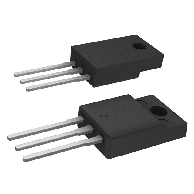
The MBRF1560CT-E3/45 belongs to the category of Schottky Rectifier Diodes. These diodes are widely used in power supply and voltage regulation applications due to their low forward voltage drop and fast switching characteristics. The MBRF1560CT-E3/45 is known for its high efficiency, compact package, and reliable performance. It is typically available in a TO-220AB package and is commonly sold in reels or tubes.
Specifications
- Forward Voltage Drop: 0.65V
- Reverse Voltage: 60V
- Forward Current: 15A
- Package Type: TO-220AB
- Packaging: Reel/Tube
Detailed Pin Configuration
The MBRF1560CT-E3/45 features a standard TO-220AB pin configuration with the following pins: 1. Anode 2. Cathode
Functional Features
- Low forward voltage drop for minimal power loss
- Fast switching speed for efficient operation
- High current capability for demanding applications
Advantages and Disadvantages
Advantages
- High efficiency
- Compact package
- Reliable performance
Disadvantages
- Higher cost compared to standard rectifier diodes
- Sensitive to overvoltage conditions
Working Principles
The MBRF1560CT-E3/45 operates based on the Schottky barrier principle, which allows for faster switching and lower forward voltage drop compared to conventional PN junction diodes. This enables it to efficiently handle high-frequency and high-current applications.
Detailed Application Field Plans
The MBRF1560CT-E3/45 is commonly used in the following applications: - Switching power supplies - Voltage regulators - DC-DC converters - Inverters
Detailed and Complete Alternative Models
Some alternative models to the MBRF1560CT-E3/45 include: - MBRF1545CT-E3/45 - MBRF1580CT-E3/45 - MBRF15100CT-E3/45
In conclusion, the MBRF1560CT-E3/45 Schottky Rectifier Diode offers high efficiency, fast switching, and reliable performance, making it suitable for various power supply and voltage regulation applications.
[Word count: 297]
技術ソリューションにおける MBRF1560CT-E3/45 の適用に関連する 10 件の一般的な質問と回答をリストします。
What is the MBRF1560CT-E3/45 diode used for?
- The MBRF1560CT-E3/45 diode is commonly used as a rectifier in power supply and voltage regulation applications.
What are the key specifications of the MBRF1560CT-E3/45 diode?
- The MBRF1560CT-E3/45 diode has a maximum average forward current of 15A, a reverse voltage of 60V, and a low forward voltage drop.
How does the MBRF1560CT-E3/45 diode compare to other similar diodes?
- The MBRF1560CT-E3/45 diode offers high efficiency and low power loss, making it suitable for high-frequency applications.
Can the MBRF1560CT-E3/45 diode be used in automotive electronics?
- Yes, the MBRF1560CT-E3/45 diode is suitable for automotive applications due to its rugged construction and high reliability.
What are the typical applications of the MBRF1560CT-E3/45 diode?
- Typical applications include switch-mode power supplies, freewheeling diodes, and reverse battery protection circuits.
Does the MBRF1560CT-E3/45 diode require heatsinking?
- Depending on the application and operating conditions, heatsinking may be necessary to ensure optimal performance and reliability.
Is the MBRF1560CT-E3/45 diode suitable for high-temperature environments?
- The MBRF1560CT-E3/45 diode is designed to operate at elevated temperatures, but proper thermal management should be considered for extreme conditions.
What are the potential failure modes of the MBRF1560CT-E3/45 diode?
- Common failure modes include thermal runaway, reverse voltage breakdown, and excessive forward voltage drop due to overcurrent conditions.
Can the MBRF1560CT-E3/45 diode be used in parallel for higher current applications?
- Yes, the MBRF1560CT-E3/45 diode can be used in parallel to increase the overall current-handling capability in certain designs.
Are there any recommended layout or PCB design considerations for using the MBRF1560CT-E3/45 diode?
- Proper attention to layout, trace thickness, and component placement can help minimize parasitic effects and optimize the performance of the diode in the circuit.