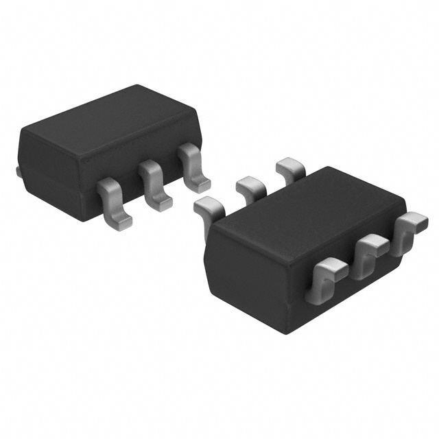
TPS22918TDBVTQ1
Product Overview
Category
The TPS22918TDBVTQ1 belongs to the category of power management integrated circuits (PMICs).
Use
This PMIC is specifically designed for managing power in automotive applications.
Characteristics
- Low on-resistance: The TPS22918TDBVTQ1 offers a low on-resistance, enabling efficient power management.
- Wide input voltage range: It can handle a wide input voltage range, making it suitable for various automotive systems.
- Overcurrent protection: The device incorporates overcurrent protection to safeguard against excessive current flow.
- Thermal shutdown: It includes a thermal shutdown feature that prevents damage due to overheating.
- ESD protection: The TPS22918TDBVTQ1 provides electrostatic discharge (ESD) protection, ensuring reliability in harsh environments.
Package and Quantity
The TPS22918TDBVTQ1 is available in a small SOT-23 package. It is typically sold in reels containing 3000 units.
Specifications
- Input Voltage Range: 2.5V to 5.5V
- On-Resistance: 40mΩ (typical)
- Quiescent Current: 0.1μA (typical)
- Operating Temperature Range: -40°C to +125°C
- Overcurrent Protection Threshold: Adjustable
Pin Configuration
The TPS22918TDBVTQ1 has the following pin configuration:
___________
      |           |
   IN |1         5| GND
   EN |2         4| OUT
   NC |3         6| NC
      |___________|
Functional Features
- Enable pin (EN): The enable pin allows the user to control the power supply to the output.
- Overcurrent protection: The device monitors the output current and protects against excessive current flow.
- Low quiescent current: The TPS22918TDBVTQ1 consumes minimal current when in standby mode, conserving power.
Advantages and Disadvantages
Advantages
- Efficient power management due to low on-resistance.
- Wide input voltage range allows for versatility in automotive applications.
- Provides overcurrent protection, ensuring system reliability.
- Thermal shutdown feature prevents damage from overheating.
- ESD protection enhances durability in harsh environments.
Disadvantages
- Limited to automotive applications, not suitable for other industries.
- SOT-23 package may require additional space compared to smaller packages.
Working Principles
The TPS22918TDBVTQ1 is a power management IC that regulates the power supply in automotive systems. It controls the flow of current from the input (IN) to the output (OUT) based on the enable pin (EN) status. When the enable pin is high, the device allows current to pass through, enabling the connected circuitry. In case of an overcurrent condition, the TPS22918TDBVTQ1 activates its protection mechanism, preventing excessive current flow and potential damage to the system.
Application Field Plans
The TPS22918TDBVTQ1 finds extensive application in various automotive systems, including:
- Infotainment systems: Power management for audio amplifiers, display modules, and touchscreen interfaces.
- Lighting systems: Control of LED headlights, taillights, and interior lighting.
- Advanced driver-assistance systems (ADAS): Power regulation for radar sensors, cameras, and lidar modules.
- Electric vehicle (EV) charging systems: Management of power distribution and battery charging circuits.
- Engine control units (ECUs): Power supply control for engine management systems.
Alternative Models
For those seeking alternative options, the following power management ICs can be considered:
- TPS22919TDBVTQ1: Similar to TPS22918TDBVTQ1 with additional features.
- TPS22920TDBVTQ1: Lower on-resistance and higher current handling capability.
- TPS22921TDBVTQ1: Enhanced ESD protection and wider input voltage range.
These alternative models offer similar functionality and can be suitable replacements based on specific requirements.
In conclusion, the TPS22918TDBVTQ1 is a power management IC designed for automotive applications. With its low on-resistance, wide input voltage range, and various protective features, it provides efficient and reliable power regulation. Its application spans across infotainment systems, lighting systems, ADAS, EV charging, and ECUs. Alternative models such as TPS22919TDBVTQ1, TPS22920TDBVTQ1, and TPS22921TDBVTQ1 offer similar functionality for different needs in the automotive industry.
技術ソリューションにおける TPS22918TDBVTQ1 の適用に関連する 10 件の一般的な質問と回答をリストします。
Sure! Here are 10 common questions and answers related to the application of TPS22918TDBVTQ1 in technical solutions:
1. What is TPS22918TDBVTQ1? - TPS22918TDBVTQ1 is a low-voltage, ultra-low RON load switch with controlled turn-on.
2. What is the typical operating voltage range for TPS22918TDBVTQ1? - The typical operating voltage range for TPS22918TDBVTQ1 is from 0.9V to 5.5V.
3. What is the maximum continuous current that TPS22918TDBVTQ1 can handle? - TPS22918TDBVTQ1 can handle a maximum continuous current of 2A.
4. How does TPS22918TDBVTQ1 help in power management? - TPS22918TDBVTQ1 helps in power management by providing an efficient way to control the power supply to various components in a system.
5. Can TPS22918TDBVTQ1 be used for hot-swapping applications? - Yes, TPS22918TDBVTQ1 can be used for hot-swapping applications as it supports controlled turn-on and provides overcurrent protection.
6. Does TPS22918TDBVTQ1 have built-in thermal shutdown protection? - Yes, TPS22918TDBVTQ1 has built-in thermal shutdown protection to prevent damage due to excessive temperature.
7. Is TPS22918TDBVTQ1 suitable for battery-powered applications? - Yes, TPS22918TDBVTQ1 is suitable for battery-powered applications as it operates at low voltages and has low quiescent current.
8. Can TPS22918TDBVTQ1 be used in automotive applications? - Yes, TPS22918TDBVTQ1 is designed for automotive applications and meets the AEC-Q100 Grade 1 qualification.
9. What is the typical response time of TPS22918TDBVTQ1? - The typical response time of TPS22918TDBVTQ1 is less than 10µs.
10. Does TPS22918TDBVTQ1 have an enable pin for controlling the load switch? - Yes, TPS22918TDBVTQ1 has an enable pin that can be used to control the load switch and turn it on or off as required.
Please note that these answers are general and may vary depending on the specific application and requirements.


