

SN74LV125ATNSR
Product Overview
Category
SN74LV125ATNSR belongs to the category of integrated circuits (ICs).
Use
It is commonly used as a quad bus buffer gate with 3-state outputs.
Characteristics
- Low-voltage operation: It operates at a voltage range of 1.65V to 5.5V.
- High-speed performance: It has a maximum propagation delay of 6.4 ns.
- 3-state outputs: The outputs can be disabled, allowing multiple devices to share a common bus.
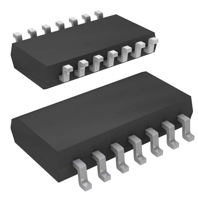
Package
SN74LV125ATNSR is available in a small-outline no-lead (SON) package.
Essence
The essence of SN74LV125ATNSR lies in its ability to provide buffering and signal isolation for digital circuits.
Packaging/Quantity
It is typically packaged in reels and comes in quantities of 2500 units per reel.
Specifications
- Supply Voltage Range: 1.65V to 5.5V
- Input Voltage Range: 0V to VCC
- Output Voltage Range: 0V to VCC
- Maximum Propagation Delay: 6.4 ns
- Operating Temperature Range: -40°C to 85°C
Detailed Pin Configuration
SN74LV125ATNSR has a total of 14 pins, which are arranged as follows:
___________
OE   -| 1       14 |- VCC
A    -| 2       13 |- Y1
B    -| 3       12 |- A1
Y2   -| 4       11 |- B1
GND  -| 5       10 |- Y3
Y4   -| 6        9 |- A2
A3   -| 7        8 |- B2
       ‾‾‾‾‾‾‾‾‾‾‾
Functional Features
- Quad Buffer Gate: SN74LV125ATNSR consists of four independent buffer gates.
- 3-State Outputs: The outputs can be enabled or disabled using the OE (Output Enable) pin.
- High-Speed Operation: It provides fast signal propagation, making it suitable for high-speed digital circuits.
Advantages and Disadvantages
Advantages
- Low-voltage operation allows compatibility with a wide range of digital systems.
- 3-state outputs enable efficient bus sharing among multiple devices.
- High-speed performance ensures quick signal transmission.
Disadvantages
- Limited number of buffer gates per IC.
- May require additional components for specific applications.
Working Principles
SN74LV125ATNSR operates by buffering and amplifying digital signals. When the OE pin is enabled, the input signals are passed through the buffer gates and amplified to the output pins. When the OE pin is disabled, the outputs are in a high-impedance state, effectively isolating them from the bus.
Detailed Application Field Plans
SN74LV125ATNSR finds applications in various fields, including:
- Microcontrollers: It can be used to interface microcontrollers with external devices, providing signal buffering and isolation.
- Communication Systems: It enables signal conditioning and level shifting in communication systems.
- Industrial Automation: It facilitates signal amplification and isolation in industrial automation equipment.
- Automotive Electronics: It can be utilized for signal buffering and level conversion in automotive electronic systems.
Detailed and Complete Alternative Models
Some alternative models that offer similar functionality to SN74LV125ATNSR include:
- SN74LVC125A: This IC offers similar characteristics and features but operates at a lower voltage range of 1.2V to 3.6V.
- SN74HCT125: It provides similar functionality but operates at a higher voltage range of 4.5V to 5.5V.
- SN74LV126A: This IC is similar to SN74LV125ATNSR but offers tri-state outputs instead of 3-state outputs.
These alternative models can be considered based on specific voltage requirements and application needs.
In conclusion, SN74LV125ATNSR is a versatile quad bus buffer gate with 3-state outputs. Its low-voltage operation, high-speed performance, and ability to provide signal buffering make it suitable for various digital applications.
技術ソリューションにおける SN74LV125ATNSR の適用に関連する 10 件の一般的な質問と回答をリストします。
Sure! Here are 10 common questions and answers related to the application of SN74LV125ATNSR:
Q: What is SN74LV125ATNSR? A: SN74LV125ATNSR is a quad bus buffer gate with 3-state outputs, commonly used in digital logic applications.
Q: What is the operating voltage range for SN74LV125ATNSR? A: The operating voltage range for SN74LV125ATNSR is typically between 1.65V and 5.5V.
Q: What is the maximum output current that SN74LV125ATNSR can drive? A: SN74LV125ATNSR can drive up to 12mA of current per output.
Q: Can SN74LV125ATNSR be used as a level shifter? A: Yes, SN74LV125ATNSR can be used as a level shifter to convert signals between different voltage levels.
Q: How many inputs and outputs does SN74LV125ATNSR have? A: SN74LV125ATNSR has 4 inputs and 4 outputs.
Q: What is the propagation delay of SN74LV125ATNSR? A: The propagation delay of SN74LV125ATNSR is typically around 4.8ns.
Q: Can SN74LV125ATNSR be used in high-speed applications? A: Yes, SN74LV125ATNSR is designed for high-speed operation and can be used in such applications.
Q: Does SN74LV125ATNSR have internal pull-up or pull-down resistors? A: No, SN74LV125ATNSR does not have internal pull-up or pull-down resistors.
Q: Can SN74LV125ATNSR be used in both CMOS and TTL logic systems? A: Yes, SN74LV125ATNSR is compatible with both CMOS and TTL logic levels.
Q: What is the package type for SN74LV125ATNSR? A: SN74LV125ATNSR is available in a small-outline integrated circuit (SOIC) package.