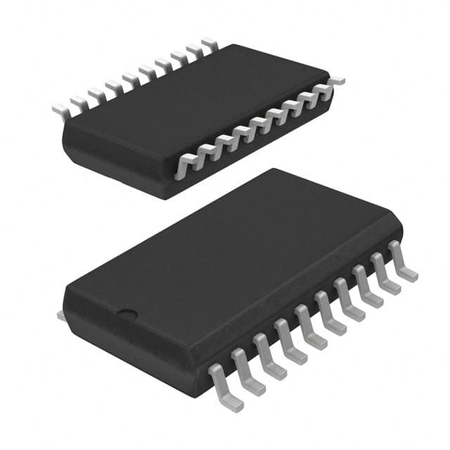
SN74ALS520DWR
Product Overview
- Category: Integrated Circuit (IC)
- Use: Logic Gate
- Characteristics: High-speed, low-power Schottky TTL technology
- Package: SOIC (Small Outline Integrated Circuit)
- Essence: 8-bit comparator with open-collector outputs
- Packaging/Quantity: Tape and Reel, 2500 units per reel
Specifications
- Supply Voltage Range: 4.5V to 5.5V
- Input Voltage Range: 0V to VCC
- Operating Temperature Range: -40°C to +85°C
- Propagation Delay Time: 9ns (typical)
- Output Current: ±8mA
- Output Voltage: 0V or VCC
Detailed Pin Configuration
The SN74ALS520DWR has a total of 20 pins, which are assigned as follows:
- A0: Input A0
- A1: Input A1
- A2: Input A2
- A3: Input A3
- A4: Input A4
- A5: Input A5
- A6: Input A6
- A7: Input A7
- GND: Ground
- B7: Input B7
- B6: Input B6
- B5: Input B5
- B4: Input B4
- B3: Input B3
- B2: Input B2
- B1: Input B1
- B0: Input B0
- O7: Output O7
- O6: Output O6
- VCC: Power Supply
Functional Features
The SN74ALS520DWR is an 8-bit comparator that compares two 8-bit binary numbers (A and B) and provides outputs indicating the relationship between them. It utilizes open-collector outputs, allowing for wired-OR connections. The device operates at high speed and low power consumption due to its Schottky TTL technology.
Advantages and Disadvantages
Advantages: - High-speed operation - Low-power consumption - Open-collector outputs for flexible wiring options
Disadvantages: - Limited voltage supply range (4.5V to 5.5V) - Propagation delay time may affect timing-sensitive applications
Working Principles
The SN74ALS520DWR compares the binary inputs A and B bit by bit. It determines whether A is greater than, equal to, or less than B. The result is indicated by the outputs O7 to O0. When an output is low, it indicates that the corresponding bit of A is less than the corresponding bit of B. When an output is high impedance (floating), it indicates that the corresponding bits are equal. The device requires a stable power supply within the specified voltage range for accurate operation.
Detailed Application Field Plans
The SN74ALS520DWR is commonly used in various digital systems where binary number comparison is required. Some application fields include:
- Arithmetic Logic Units (ALUs)
- Microcontrollers
- Digital Signal Processors (DSPs)
- Data processing units
- Communication systems
Detailed and Complete Alternative Models
- SN74ALS521DWR: 8-bit comparator with tri-state outputs
- SN74ALS522DWR: 8-bit magnitude comparator with open-collector outputs
- SN74ALS523DWR: 8-bit magnitude comparator with tri-state outputs
- SN74ALS524DWR: 8-bit magnitude comparator with latch enable
These alternative models offer similar functionality with slight variations in features and output types.
Word count: 346 words
技術ソリューションにおける SN74ALS520DWR の適用に関連する 10 件の一般的な質問と回答をリストします。
Sure! Here are 10 common questions and answers related to the application of SN74ALS520DWR:
Q: What is SN74ALS520DWR? A: SN74ALS520DWR is a specific integrated circuit (IC) chip, commonly known as a multiplexer/demultiplexer. It can be used to select one of multiple input signals and route it to a single output.
Q: What are the typical applications of SN74ALS520DWR? A: SN74ALS520DWR is often used in digital systems where multiple data sources need to be selectively routed to a single destination, such as in communication systems, data acquisition systems, or control systems.
Q: How many inputs does SN74ALS520DWR have? A: SN74ALS520DWR has 8 input channels, allowing you to choose from up to 8 different input signals.
Q: Can I use SN74ALS520DWR as a demultiplexer? A: Yes, SN74ALS520DWR can function as both a multiplexer and a demultiplexer. By configuring its control inputs appropriately, you can use it to route a single input signal to one of multiple outputs.
Q: What is the voltage range supported by SN74ALS520DWR? A: SN74ALS520DWR operates with a supply voltage range of 4.5V to 5.5V.
Q: What is the maximum data rate supported by SN74ALS520DWR? A: SN74ALS520DWR can handle data rates up to 25 MHz, making it suitable for many high-speed digital applications.
Q: Does SN74ALS520DWR have any built-in protection features? A: Yes, SN74ALS520DWR has built-in electrostatic discharge (ESD) protection on all inputs and outputs, providing some level of immunity against static electricity.
Q: Can I cascade multiple SN74ALS520DWR chips together? A: Yes, you can cascade multiple SN74ALS520DWR chips to increase the number of input channels or output channels, allowing for more complex signal routing.
Q: What is the power consumption of SN74ALS520DWR? A: The power consumption of SN74ALS520DWR depends on various factors such as the supply voltage, data rate, and load conditions. It is recommended to refer to the datasheet for detailed information.
Q: Are there any specific layout considerations when using SN74ALS520DWR? A: Yes, it is important to follow the recommended layout guidelines provided in the datasheet to ensure proper signal integrity and minimize noise interference.


