

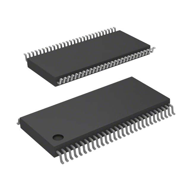
SN74ABT16501DGGR
Product Overview
- Category: Integrated Circuit (IC)
- Use: Data storage and transfer
- Characteristics: High-speed, bidirectional, 18-bit universal shift register
- Package: TSSOP-56
- Essence: Efficient data manipulation and transfer
- Packaging/Quantity: Tape and Reel, 2500 units per reel
Specifications
- Number of Bits: 18
- Logic Family: ABT
- Supply Voltage Range: 4.5V to 5.5V
- Input/Output Type: Tri-State
- Operating Temperature Range: -40°C to +85°C
- Output Current: ±24mA
- Propagation Delay: 3.8ns (typical)
Detailed Pin Configuration
The SN74ABT16501DGGR has a total of 56 pins, which are distributed as follows:
- GND (Ground)
- D1 (Data Input 1)
- D2 (Data Input 2)
- D3 (Data Input 3)
- D4 (Data Input 4)
- D5 (Data Input 5)
- D6 (Data Input 6)
- D7 (Data Input 7)
- D8 (Data Input 8)
- D9 (Data Input 9)
- D10 (Data Input 10)
- D11 (Data Input 11)
- D12 (Data Input 12)
- D13 (Data Input 13)
- D14 (Data Input 14)
- D15 (Data Input 15)
- D16 (Data Input 16)
- D17 (Data Input 17)
- D18 (Data Input 18)
- VCC (Supply Voltage)
- GND (Ground)
- OE (Output Enable)
- CP (Clock Pulse)
- DS (Serial Data Input)
- SHCP (Shift Clock Pulse)
- STCP (Storage Clock Pulse)
- Q1 (Serial Output 1)
- Q2 (Serial Output 2)
- Q3 (Serial Output 3)
- Q4 (Serial Output 4)
- Q5 (Serial Output 5)
- Q6 (Serial Output 6)
- Q7 (Serial Output 7)
- Q8 (Serial Output 8)
- Q9 (Serial Output 9)
- Q10 (Serial Output 10)
- Q11 (Serial Output 11)
- Q12 (Serial Output 12)
- Q13 (Serial Output 13)
- Q14 (Serial Output 14)
- Q15 (Serial Output 15)
- Q16 (Serial Output 16)
- Q17 (Serial Output 17)
- Q18 (Serial Output 18)
- GND (Ground)
Functional Features
- Bidirectional data transfer
- High-speed operation
- Tri-state outputs for bus sharing
- Serial or parallel data loading
- Shift and storage clock inputs for synchronized operation
- Wide supply voltage range for compatibility
Advantages and Disadvantages
Advantages: - High-speed operation allows for efficient data transfer - Bidirectional functionality enables versatile usage - Tri-state outputs facilitate bus sharing - Wide supply voltage range ensures compatibility with various systems
Disadvantages: - Limited number of bits (18) may not be sufficient for certain applications - TSSOP package may require careful handling during assembly
Working Principles
The SN74ABT16501DGGR is a universal shift register that can store and transfer data in both directions. It operates based on clock pulses and serial or parallel data loading. The shift clock pulse (SHCP) controls the shifting of data, while the storage clock pulse (STCP) determines when the data is stored in the register. The output enable (OE) pin enables or disables the outputs, allowing for bus sharing.
Detailed Application Field Plans
The SN74ABT16501DGGR can be used in various applications that require efficient data storage and transfer. Some potential application fields include:
- Communication Systems: Used for data buffering and synchronization in communication protocols such as UART, SPI, and I2C.
- Data Acquisition: Enables the collection and processing of data from sensors and other sources.
- Industrial Automation: Facilitates control and monitoring systems by handling input and output data.
- Test and Measurement Equipment: Provides accurate data acquisition and analysis capabilities.
- Automotive Electronics: Supports data transfer and control functions in automotive systems.
Detailed and Complete Alternative Models
- SN74ABT16500DLR: 18-bit universal shift register with similar features but different package (SOIC-56).
技術ソリューションにおける SN74ABT16501DGGR の適用に関連する 10 件の一般的な質問と回答をリストします。
Sure! Here are 10 common questions and answers related to the application of SN74ABT16501DGGR:
Q: What is SN74ABT16501DGGR? A: SN74ABT16501DGGR is a 16-bit universal bus transceiver with 3-state outputs, designed for asynchronous communication between data buses.
Q: What is the operating voltage range of SN74ABT16501DGGR? A: The operating voltage range of SN74ABT16501DGGR is typically between 4.5V and 5.5V.
Q: Can SN74ABT16501DGGR be used in both input and output modes? A: Yes, SN74ABT16501DGGR can be used as both an input and output device, allowing bidirectional data transfer.
Q: What is the maximum data transfer rate supported by SN74ABT16501DGGR? A: SN74ABT16501DGGR supports a maximum data transfer rate of 200 MHz.
Q: How many 3-state outputs does SN74ABT16501DGGR have? A: SN74ABT16501DGGR has 16 3-state outputs, one for each bit of the data bus.
Q: Can SN74ABT16501DGGR handle multiple voltage levels? A: No, SN74ABT16501DGGR operates at a single voltage level and is not designed to handle multiple voltage levels.
Q: What is the purpose of the OE (Output Enable) pin on SN74ABT16501DGGR? A: The OE pin is used to enable or disable the outputs of SN74ABT16501DGGR. When OE is high, the outputs are enabled; when OE is low, the outputs are disabled.
Q: Can SN74ABT16501DGGR be cascaded to increase the number of bits? A: Yes, multiple SN74ABT16501DGGR devices can be cascaded together to increase the number of bits in the data bus.
Q: What is the typical power consumption of SN74ABT16501DGGR? A: The typical power consumption of SN74ABT16501DGGR is around 20mW.
Q: Is SN74ABT16501DGGR suitable for high-speed applications? A: Yes, SN74ABT16501DGGR is designed for high-speed applications and can handle fast data transfer rates.
Please note that these answers are general and may vary depending on specific application requirements. It's always recommended to refer to the datasheet and consult with technical experts for accurate information.