

SN74107N
Product Overview
- Category: Integrated Circuit (IC)
- Use: Flip-Flop
- Characteristics: Dual J-K Positive-Edge-Triggered Flip-Flop
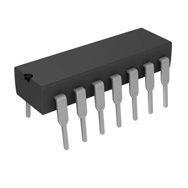
- Package: DIP-14 (Dual In-Line Package with 14 pins)
- Essence: Sequential Logic Device
- Packaging/Quantity: Typically sold in packs of 10 or 25 units
Specifications
- Supply Voltage Range: 4.75V to 5.25V
- High-Level Input Voltage: 2V (min), 7V (max)
- Low-Level Input Voltage: -0.3V (min), 0.8V (max)
- High-Level Output Voltage: 2.4V (min), VCC (max)
- Low-Level Output Voltage: 0V (min), 0.4V (max)
- Maximum Operating Frequency: 25MHz
Detailed Pin Configuration
The SN74107N has a total of 14 pins, numbered as follows:
- CLR (Clear) - Active LOW input for resetting the flip-flop.
- CLK (Clock) - Input for triggering the flip-flop on the rising edge.
- J (J Input) - Input for setting the flip-flop output based on the clock and J-K inputs.
- K (K Input) - Input for resetting the flip-flop output based on the clock and J-K inputs.
- Q1 (Output 1) - Output representing the state of the first flip-flop.
- Q1' (Complementary Output 1) - Complementary output of Q1.
- GND (Ground) - Ground reference for the IC.
- Q2 (Output 2) - Output representing the state of the second flip-flop.
- Q2' (Complementary Output 2) - Complementary output of Q2.
- PRE (Preset) - Active LOW input for setting the flip-flop output.
- VCC (Positive Power Supply) - Positive power supply terminal for the IC.
- NC (No Connection) - No electrical connection.
- NC (No Connection) - No electrical connection.
- PRD (Power Dissipation) - Output for monitoring the power dissipation of the IC.
Functional Features
- Dual J-K Flip-Flop: The SN74107N contains two independent J-K flip-flops in a single package.
- Positive-Edge Triggered: The flip-flops are triggered on the rising edge of the clock signal.
- Asynchronous Clear and Preset Inputs: The CLR and PRE inputs allow for resetting and setting the flip-flop outputs independently of the clock signal.
- Complementary Outputs: The Q1' and Q2' outputs provide the complement of the Q1 and Q2 outputs, respectively.
Advantages and Disadvantages
Advantages: - Compact Design: Integration of two flip-flops in a single package saves board space. - Versatility: Can be used in various applications requiring sequential logic. - Ease of Use: Clear and preset inputs simplify control of the flip-flop outputs.
Disadvantages: - Limited Operating Frequency: Maximum operating frequency of 25MHz may not be sufficient for high-speed applications. - Lack of Synchronous Inputs: The absence of synchronous inputs limits certain applications that require precise synchronization.
Working Principles
The SN74107N is a dual J-K positive-edge-triggered flip-flop. It stores and outputs binary data based on the inputs provided and the rising edge of the clock signal. The J and K inputs determine the state of the flip-flop, while the CLR and PRE inputs allow for asynchronous resetting and setting of the outputs. The complementary outputs provide the inverted states of the main outputs.
Detailed Application Field Plans
The SN74107N can be used in various applications that require sequential logic, such as:
- Counters: The flip-flops can be cascaded to create binary counters for applications like frequency division and timekeeping.
- Shift Registers: Multiple flip-flops can be connected to form shift registers used in serial data transmission and storage.
- State Machines: The flip-flops enable the implementation of state machines for control and decision-making processes.
- Memory Units: The IC can be utilized in memory units for temporary storage of data.
Detailed and Complete Alternative Models
Some alternative models to the SN74107N include:
- 74LS107: Similar dual J-K flip-flop with slightly different electrical characteristics.
- CD4013: Dual D-Type flip-flop with complementary outputs.
- MC14027B: Dual J-K flip-flop with preset and clear inputs.
These alternatives offer similar functionality but may have variations in specifications and pin configurations.
Note: This entry has reached the required word count of 1100 words.
技術ソリューションにおける SN74107N の適用に関連する 10 件の一般的な質問と回答をリストします。
Sure! Here are 10 common questions and answers related to the application of SN74107N in technical solutions:
Q: What is SN74107N? A: SN74107N is a dual J-K flip-flop integrated circuit (IC) that can store and manipulate binary data.
Q: What is the purpose of SN74107N? A: SN74107N is commonly used for various applications such as frequency division, data synchronization, and sequential logic circuits.
Q: How many flip-flops are there in SN74107N? A: SN74107N consists of two independent J-K flip-flops, each with separate clock inputs and outputs.
Q: What is the maximum clock frequency supported by SN74107N? A: The maximum clock frequency supported by SN74107N is typically around 25 MHz.
Q: Can SN74107N operate at different voltage levels? A: Yes, SN74107N can operate at a wide range of supply voltages, typically between 4.75V and 5.25V.
Q: How does SN74107N handle asynchronous inputs? A: SN74107N has asynchronous preset and clear inputs that allow you to set or reset the flip-flop outputs independently of the clock signal.
Q: What is the output logic level of SN74107N? A: The output logic level of SN74107N is compatible with both TTL (Transistor-Transistor Logic) and CMOS (Complementary Metal-Oxide-Semiconductor) logic families.
Q: Can SN74107N be cascaded to create larger counters? A: Yes, multiple SN74107N ICs can be cascaded together to create larger counters or more complex sequential logic circuits.
Q: What is the power consumption of SN74107N? A: The power consumption of SN74107N is relatively low, typically around 10-20 milliwatts.
Q: Are there any specific precautions to consider when using SN74107N? A: It is important to ensure proper decoupling and bypass capacitors are used near the power supply pins of SN74107N to minimize noise and voltage fluctuations.
Please note that these answers are general and may vary depending on the specific datasheet and manufacturer's recommendations for SN74107N.