

PCA9539PWE4
Product Overview
Category
PCA9539PWE4 belongs to the category of integrated circuits (ICs).
Use
The PCA9539PWE4 is a versatile 16-bit I2C-bus I/O expander designed for general-purpose input/output expansion applications. It provides remote I/O expansion for most microcontroller families via the I2C-bus interface.
Characteristics
- 16-bit remote bidirectional I/O port
- Compatible with I2C-bus standard mode and Fast-mode
- Low standby current consumption
- Schmitt trigger inputs for noise suppression
- Internal power-on reset
- Noise filter on SCL/SDA inputs
- No glitch on power-up
- Latched outputs with high-current drive capability for directly driving LEDs
- Output state change programmable on the Acknowledge or Stop command
- Active LOW interrupt output
- ESD protection exceeds 2000 V HBM per JESD22-A114, 200 V MM per JESD22-A115, and 1000 V CDM per JESD22-C101
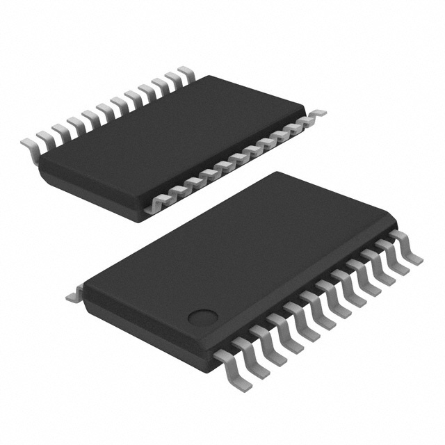
Package
The PCA9539PWE4 comes in a TSSOP package.
Essence
The essence of PCA9539PWE4 lies in its ability to expand the input/output capabilities of microcontrollers through the I2C-bus interface.
Packaging/Quantity
The PCA9539PWE4 is typically packaged in reels and available in quantities of 2500 units per reel.
Specifications
- Supply Voltage: 2.3 V to 5.5 V
- Input Voltage Range: GND to VDD
- Operating Temperature Range: -40°C to +85°C
- I2C-bus Frequency: 100 kHz and 400 kHz
- Maximum Output Current: 25 mA per channel
- Maximum Standby Current: 1 μA
Detailed Pin Configuration
The PCA9539PWE4 has a total of 24 pins. The pin configuration is as follows:
- SDA - Serial Data Input/Output
- SCL - Serial Clock Input
- A0 - Address Input
- A1 - Address Input
- A2 - Address Input 6-21. P0-P15 - General Purpose I/O Pins
- INT - Interrupt Output
- VDD - Supply Voltage
- GND - Ground
Functional Features
- Bidirectional I/O Expansion: The PCA9539PWE4 provides 16 bidirectional I/O ports, allowing for flexible input and output expansion.
- I2C-bus Interface: It communicates with microcontrollers through the I2C-bus interface, enabling easy integration into existing systems.
- Latched Outputs: The outputs have latching capability and can drive high currents, making it suitable for driving LEDs directly.
- Noise Suppression: Schmitt trigger inputs and noise filters ensure reliable operation in noisy environments.
- Power-On Reset: The internal power-on reset feature ensures proper initialization upon power-up.
Advantages and Disadvantages
Advantages
- Versatile I/O expansion solution
- Low standby current consumption
- Robust ESD protection
- Easy integration with microcontrollers
- High-current drive capability for LEDs
Disadvantages
- Limited to 16 I/O ports
- Requires an I2C-bus interface for communication
Working Principles
The PCA9539PWE4 operates by communicating with a microcontroller through the I2C-bus interface. It receives commands from the microcontroller and performs the corresponding input or output operations on its 16 bidirectional I/O ports. The latched outputs allow for driving LEDs or other devices directly. The device also features noise suppression and power-on reset for reliable operation.
Detailed Application Field Plans
The PCA9539PWE4 finds applications in various fields, including but not limited to: - Industrial automation - Home automation - Automotive electronics - Internet of Things (IoT) devices - Robotics - Consumer electronics
In industrial automation, it can be used for controlling sensors, actuators, and other peripheral devices. In home automation, it enables the control of lighting systems, appliances, and security devices. In automotive electronics, it can be utilized for controlling lights, switches, and other vehicle functions. In IoT devices, it provides I/O expansion capabilities for sensor nodes and edge devices. In robotics, it facilitates the control of motors, sensors, and communication interfaces. In consumer electronics, it can be employed for user interface controls, LED indicators, and more.
Detailed and Complete Alternative Models
Some alternative models to PCA9539PWE4 that offer similar functionality include: - MCP23017 - PCF8574 - MAX7313 - TCA9539 - SX1509
These alternatives provide comparable I
技術ソリューションにおける PCA9539PWE4 の適用に関連する 10 件の一般的な質問と回答をリストします。
Sure! Here are 10 common questions and answers related to the application of PCA9539PWE4:
Q: What is PCA9539PWE4? A: PCA9539PWE4 is a 16-bit I/O expander with an I2C interface, which allows for easy expansion of digital I/O ports in various technical solutions.
Q: What is the maximum voltage that PCA9539PWE4 can handle? A: PCA9539PWE4 can handle a maximum voltage of 5.5V.
Q: How many I/O pins does PCA9539PWE4 have? A: PCA9539PWE4 has 16 I/O pins that can be configured as either inputs or outputs.
Q: Can PCA9539PWE4 be used to control LEDs? A: Yes, PCA9539PWE4 can be used to control LEDs by configuring its I/O pins as outputs and connecting them to the LED circuitry.
Q: Is PCA9539PWE4 compatible with Arduino boards? A: Yes, PCA9539PWE4 can be used with Arduino boards by connecting it to the I2C pins (SDA and SCL) on the Arduino.
Q: Can PCA9539PWE4 be used to read analog signals? A: No, PCA9539PWE4 is a digital I/O expander and cannot directly read analog signals. It can only handle digital inputs and outputs.
Q: How do I communicate with PCA9539PWE4 using the I2C interface? A: You can communicate with PCA9539PWE4 using the I2C protocol by sending appropriate commands and data over the I2C bus.
Q: Can PCA9539PWE4 be used in automotive applications? A: Yes, PCA9539PWE4 is suitable for automotive applications as it can handle the required voltage levels and has a wide operating temperature range.
Q: What is the maximum current that PCA9539PWE4 can sink/source per I/O pin? A: PCA9539PWE4 can sink/source up to 25mA per I/O pin.
Q: Can multiple PCA9539PWE4 devices be connected together on the same I2C bus? A: Yes, multiple PCA9539PWE4 devices can be connected together on the same I2C bus by assigning unique addresses to each device using the address pins (A0, A1, A2).