

LM3914V
Product Overview
Category: Integrated Circuit (IC)
Use: The LM3914V is a versatile analog display driver IC that can be used to drive a wide range of LED-based displays. It is commonly used in applications where visual representation of data or information is required, such as audio level indicators, VU meters, battery monitors, and signal strength meters.
Characteristics: - Voltage Range: 3V to 25V - Number of Outputs: 10 - Output Current: Up to 30mA per channel - Display Type: Bar graph or dot mode - Low Power Consumption: Typically 3mA - Temperature Range: -40°C to +85°C
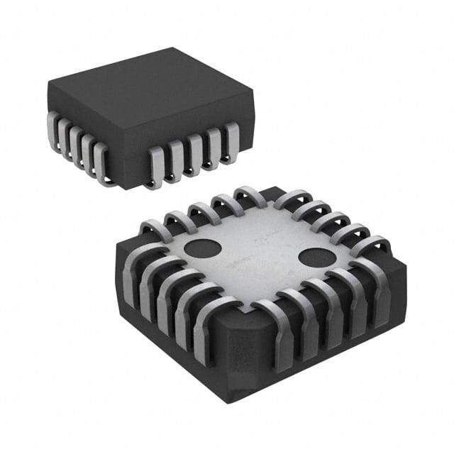
Package: The LM3914V is available in a standard 18-pin DIP (Dual Inline Package) format, which makes it easy to integrate into various electronic circuits.
Essence: The essence of the LM3914V lies in its ability to convert an analog input voltage into a corresponding visual display on a series of LEDs. This allows for intuitive and easy-to-read representations of data or information.
Packaging/Quantity: The LM3914V is typically sold in reels or tubes, with each reel containing 2,500 units or each tube containing 50 units.
Specifications
The LM3914V has the following specifications:
- Supply Voltage Range: 3V to 25V
- Input Voltage Range: 0V to Vcc
- Output Voltage Range: 0V to Vcc
- Output Current Range: 1mA to 30mA
- Reference Voltage: Adjustable from 1.2V to Vcc
- Internal Voltage Reference Accuracy: ±1.5%
- LED Driver Output Voltage Drop: Typically 1.2V
- LED Driver Output Current Accuracy: ±3%
Pin Configuration
The LM3914V has 18 pins, each serving a specific function. The detailed pin configuration is as follows:
- V+ (Positive Supply Voltage)
- REF OUT (Reference Output)
- REF ADJ (Reference Adjust)
- V- (Negative Supply Voltage)
- GND (Ground)
- LED10 (LED Driver Output 10)
- LED9 (LED Driver Output 9)
- LED8 (LED Driver Output 8)
- LED7 (LED Driver Output 7)
- LED6 (LED Driver Output 6)
- LED5 (LED Driver Output 5)
- LED4 (LED Driver Output 4)
- LED3 (LED Driver Output 3)
- LED2 (LED Driver Output 2)
- LED1 (LED Driver Output 1)
- LED0 (LED Driver Output 0)
- MODE (Mode Select)
- RLO (Ripple Blanking Output)
Functional Features
The LM3914V offers the following functional features:
- Bar Graph or Dot Mode: The display can be configured to operate in either bar graph mode, where the LEDs form a continuous bar, or dot mode, where each LED represents an individual step.
- Adjustable Reference Voltage: The reference voltage can be adjusted using an external resistor, allowing for precise control over the display range.
- Cascading Capability: Multiple LM3914V ICs can be cascaded together to drive larger displays with more LEDs.
- Low Power Consumption: The IC operates at low power, making it suitable for battery-powered applications.
- Internal Ripple Blanking: The ripple blanking output can be used to suppress unwanted display flickering caused by AC ripple.
Advantages and Disadvantages
Advantages: - Versatile and widely used in various applications - Easy integration into electronic circuits - Precise control over display range - Low power consumption - Cascading capability for larger displays
Disadvantages: - Limited number of output channels (10) - Requires external components for reference voltage adjustment
Working Principles
The LM3914V operates based on the principle of analog-to-digital conversion. The input voltage is compared to a reference voltage, and depending on the result, the corresponding LED outputs are turned on or off. The IC uses an internal voltage divider network and a series of comparators to achieve this functionality.
Detailed Application Field Plans
The LM3914V finds applications in various fields, including:
- Audio Equipment: It can be used as an audio level indicator or VU meter to visualize sound levels.
- Battery Monitors: It can monitor the voltage level of batteries and provide a visual indication of their charge status.
- Signal Strength Meters: It can be used to measure and display the strength of signals in communication systems.
- Power Supplies: It can indicate the output voltage level of power supplies, ensuring proper functioning.
- Automotive Electronics: It can be used
技術ソリューションにおける LM3914V の適用に関連する 10 件の一般的な質問と回答をリストします。
Sure! Here are 10 common questions and answers related to the application of LM3914V:
Q: What is LM3914V? A: LM3914V is a popular integrated circuit (IC) used for driving a series of LEDs in a bar graph display.
Q: What is the operating voltage range of LM3914V? A: The operating voltage range of LM3914V is typically between 3V and 25V.
Q: How many LEDs can be driven by LM3914V? A: LM3914V can drive up to 10 LEDs, making it suitable for bar graph displays with 10 segments.
Q: Can LM3914V be used to control individual LEDs? A: No, LM3914V is designed to drive LEDs as a bar graph display and does not provide individual LED control.
Q: How does LM3914V determine the brightness of each LED? A: LM3914V uses a voltage divider network to divide the input voltage into 10 equal segments, each corresponding to an LED's brightness level.
Q: Can LM3914V be used with different types of LEDs? A: Yes, LM3914V can be used with various types of LEDs, including common cathode and common anode configurations.
Q: Can LM3914V be cascaded to drive more than 10 LEDs? A: Yes, multiple LM3914V ICs can be cascaded together to drive more than 10 LEDs in a bar graph display.
Q: Is LM3914V capable of logarithmic or linear display modes? A: LM3914V supports both logarithmic (dB) and linear display modes, which can be selected using external resistors.
Q: Can LM3914V be used in automotive applications? A: Yes, LM3914V is commonly used in automotive applications such as audio level indicators and battery voltage monitors.
Q: Are there any specific precautions to consider when using LM3914V? A: It is important to ensure that the power supply voltage does not exceed the maximum rating of 25V. Additionally, proper decoupling capacitors should be used for stable operation.
Please note that these answers are general and may vary depending on the specific application and circuit design.