

CD74HC04E
Product Overview
- Category: Integrated Circuit
- Use: Inverter Gate
- Characteristics: High-Speed CMOS Logic, Hex Inverter
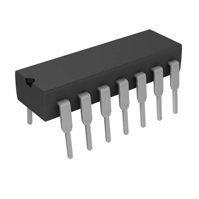
- Package: 14-Pin DIP (Dual Inline Package)
- Essence: The CD74HC04E is a high-speed CMOS logic integrated circuit that consists of six inverter gates. It is commonly used for signal inversion and amplification in various electronic circuits.
- Packaging/Quantity: Available in reels or tubes with varying quantities.
Specifications
- Supply Voltage: 2V to 6V
- Input Voltage: 0V to VCC
- Output Voltage: 0V to VCC
- Operating Temperature: -55°C to +125°C
- Propagation Delay: 9 ns (typical)
Pin Configuration
The CD74HC04E has a 14-pin Dual Inline Package (DIP) with the following pin configuration:
__    __
   Y1 | 1  \/ 14 | VCC
   A1 | 2      13 | A6
   B1 | 3      12 | Y6
   A2 | 4      11 | B6
   Y2 | 5      10 | A5
   B2 | 6       9 | Y5
   A3 | 7       8 | B5
        ¯¯    ¯¯
Functional Features
- High-Speed Operation: The CD74HC04E offers fast switching speeds, making it suitable for applications requiring quick signal processing.
- Wide Operating Voltage Range: It can operate within a voltage range of 2V to 6V, providing flexibility in different electronic systems.
- Low Power Consumption: The CMOS technology used in the CD74HC04E ensures low power consumption, making it energy-efficient.
Advantages and Disadvantages
Advantages: - High-speed operation allows for efficient signal processing. - Wide operating voltage range provides versatility in various applications. - Low power consumption contributes to energy efficiency.
Disadvantages: - Limited number of inverter gates (six in total) may restrict complex circuit designs. - Sensitivity to electrostatic discharge (ESD) requires proper handling during installation and usage.
Working Principles
The CD74HC04E operates based on the principles of CMOS logic. Each inverter gate within the IC consists of complementary MOS transistors that control the flow of current. When an input signal is applied, the output signal is inverted, i.e., a high input results in a low output and vice versa.
Detailed Application Field Plans
The CD74HC04E finds application in various electronic systems, including but not limited to: 1. Digital Logic Circuits: It can be used as a basic building block for constructing digital logic circuits such as flip-flops, counters, and registers. 2. Signal Conditioning: The inverter gate functionality makes it suitable for signal conditioning applications, where signal inversion or amplification is required. 3. Oscillator Circuits: It can be utilized in oscillator circuits to generate clock signals for synchronous operations. 4. Data Communication Systems: The CD74HC04E can be employed in data communication systems for signal conversion and level shifting.
Detailed and Complete Alternative Models
Some alternative models to the CD74HC04E include: - SN74HC04N - MC74HC04AN - 74HCT04
These alternatives offer similar functionality and characteristics, providing options for different design requirements.
Word count: 334 words
技術ソリューションにおける CD74HC04E の適用に関連する 10 件の一般的な質問と回答をリストします。
Sure! Here are 10 common questions and answers related to the application of CD74HC04E in technical solutions:
Q: What is CD74HC04E? A: CD74HC04E is a hex inverter integrated circuit (IC) that consists of six independent inverters. It is commonly used in digital logic circuits.
Q: What is the voltage supply range for CD74HC04E? A: The voltage supply range for CD74HC04E is typically between 2V and 6V.
Q: What is the maximum output current of CD74HC04E? A: The maximum output current of CD74HC04E is around 5.2mA.
Q: Can CD74HC04E be used as a level shifter? A: Yes, CD74HC04E can be used as a level shifter to convert signals from one voltage level to another.
Q: How many inputs and outputs does CD74HC04E have? A: CD74HC04E has six inputs and six corresponding outputs.
Q: What is the propagation delay of CD74HC04E? A: The propagation delay of CD74HC04E is typically around 9ns.
Q: Can CD74HC04E be used in high-speed applications? A: Yes, CD74HC04E is suitable for high-speed applications due to its fast switching characteristics.
Q: Is CD74HC04E compatible with TTL logic levels? A: Yes, CD74HC04E is compatible with TTL logic levels, making it versatile for various interfacing applications.
Q: Can CD74HC04E drive capacitive loads? A: Yes, CD74HC04E can drive capacitive loads, but it is recommended to use a series resistor to limit the current.
Q: What are some common applications of CD74HC04E? A: CD74HC04E is commonly used in digital systems, such as signal inversion, waveform generation, clock buffering, and logic level conversion.
Please note that these answers are general and may vary depending on specific datasheet specifications and application requirements.