

P4KE51A R1G
Product Overview
Category
The P4KE51A R1G belongs to the category of transient voltage suppressor diodes.
Use
It is used to protect electronic circuits from overvoltage transients.
Characteristics
- Fast response time
- Low clamping voltage
- High surge capability
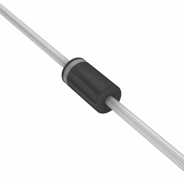
Package
The P4KE51A R1G is available in a DO-41 package.
Essence
This diode serves as a crucial component in safeguarding sensitive electronic devices from voltage spikes.
Packaging/Quantity
The P4KE51A R1G is typically packaged in reels and is available in quantities of 500 or 1000 units per reel.
Specifications
- Peak Power Dissipation: 400W
- Breakdown Voltage: 45.2V
- Maximum Clamping Voltage: 77.4V
- Operating Temperature Range: -55°C to 175°C
Detailed Pin Configuration
The P4KE51A R1G has two pins, anode (A) and cathode (K), which are clearly marked on the diode body.
Functional Features
- Transient voltage suppression
- Reverse avalanche breakdown protection
- Fast response to voltage transients
Advantages
- Robust protection against voltage surges
- Fast reaction time
- Wide operating temperature range
Disadvantages
- Limited power dissipation capability
- Requires proper installation for effective protection
Working Principles
When a voltage transient occurs, the P4KE51A R1G conducts and clamps the voltage to a safe level, protecting the connected circuitry from damage.
Detailed Application Field Plans
The P4KE51A R1G is commonly used in: - Power supplies - Telecommunication equipment - Automotive electronics - Industrial control systems
Detailed and Complete Alternative Models
- P4KE6.8A R1G
- P4KE10A R1G
- P4KE18A R1G
- P4KE30A R1G
In conclusion, the P4KE51A R1G transient voltage suppressor diode offers robust protection against voltage transients, making it an essential component in various electronic applications.
[Word count: 298]
技術ソリューションにおける P4KE51A R1G の適用に関連する 10 件の一般的な質問と回答をリストします。
What is P4KE51A R1G?
- P4KE51A R1G is a type of transient voltage suppressor diode used to protect electronic circuits from voltage spikes and transients.
What are the key features of P4KE51A R1G?
- P4KE51A R1G features include a peak pulse power of 400W, low clamping voltage, fast response time, and high surge current capability.
Where is P4KE51A R1G commonly used in technical solutions?
- P4KE51A R1G is commonly used in applications such as power supplies, automotive electronics, industrial equipment, and telecommunications systems for transient voltage protection.
How does P4KE51A R1G provide protection in technical solutions?
- P4KE51A R1G protects against voltage spikes by diverting excess current away from sensitive components, thereby preventing damage to the circuit.
What is the operating temperature range of P4KE51A R1G?
- The operating temperature range of P4KE51A R1G typically ranges from -55°C to 175°C, making it suitable for various environmental conditions.
Are there any specific mounting or handling considerations for P4KE51A R1G?
- P4KE51A R1G should be mounted on a heat sink or thermal pad to dissipate heat effectively, and proper ESD precautions should be taken during handling to prevent damage.
What are the industry standards or certifications associated with P4KE51A R1G?
- P4KE51A R1G may comply with industry standards such as RoHS (Restriction of Hazardous Substances) and may have relevant certifications from regulatory bodies.
Can P4KE51A R1G be used in high-frequency applications?
- P4KE51A R1G can be used in high-frequency applications due to its fast response time and low capacitance characteristics.
What are the typical failure modes of P4KE51A R1G?
- Typical failure modes of P4KE51A R1G may include short-circuit failure due to excessive current or open-circuit failure if subjected to extreme voltage stress.
How can P4KE51A R1G be integrated into a technical solution for optimal performance?
- P4KE51A R1G should be carefully selected based on the application's voltage and current requirements, and proper circuit layout and design considerations should be followed to ensure effective integration and performance.