

RJK6013DPE-00#J3
Product Overview
Category
The RJK6013DPE-00#J3 belongs to the category of power MOSFETs.
Use
It is used as a high-speed switching device in various electronic circuits and power supply applications.
Characteristics
- High-speed switching capability
- Low on-state resistance
- Low gate charge
- Enhanced ruggedness and reliability
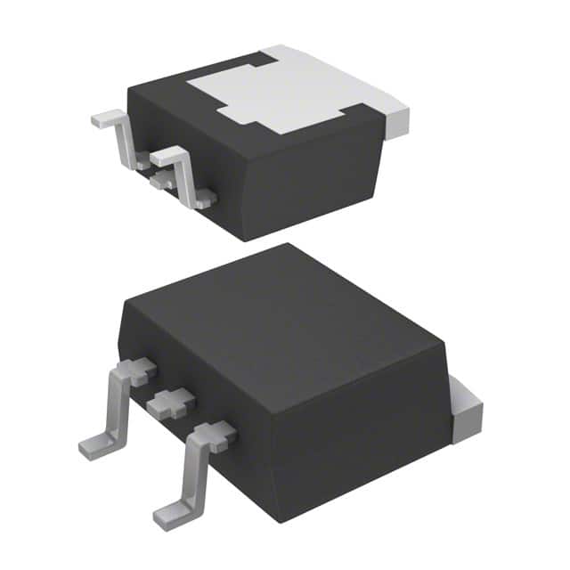
Package
The RJK6013DPE-00#J3 is typically available in a TO-220 package.
Essence
This MOSFET is designed to efficiently control and switch high-power loads in electronic circuits.
Packaging/Quantity
The RJK6013DPE-00#J3 is commonly packaged in reels or tubes, with quantities varying based on manufacturer specifications.
Specifications
- Drain-Source Voltage (VDS): 600V
- Continuous Drain Current (ID): 45A
- On-State Resistance (RDS(on)): 0.13Ω
- Gate-Source Voltage (VGS): ±30V
- Total Gate Charge (Qg): 40nC
- Operating Temperature Range: -55°C to 150°C
Detailed Pin Configuration
The RJK6013DPE-00#J3 features a standard pin configuration with three pins: Gate (G), Drain (D), and Source (S).
Functional Features
- Fast switching speed for improved efficiency
- Low on-state resistance minimizes power loss
- Enhanced ruggedness for reliable performance in demanding applications
Advantages and Disadvantages
Advantages
- High-speed switching capability
- Low on-state resistance reduces power dissipation
- Enhanced reliability and ruggedness
Disadvantages
- Higher gate capacitance may require careful driver design for optimal performance
- Limited voltage and current ratings compared to some alternative models
Working Principles
The RJK6013DPE-00#J3 operates based on the principles of field-effect transistors, utilizing the control of electric fields to modulate the conductivity of the semiconductor material.
Detailed Application Field Plans
The RJK6013DPE-00#J3 is suitable for a wide range of applications, including: - Switching power supplies - Motor control circuits - Inverters and converters - Electronic ballasts - Audio amplifiers
Detailed and Complete Alternative Models
Some alternative models to the RJK6013DPE-00#J3 include: - IRF540N - FDP8870 - STP55NF06L - AOT240L
Note: The provided alternatives are for reference purposes and may vary based on specific application requirements.
This comprehensive entry provides an in-depth understanding of the RJK6013DPE-00#J3, covering its basic information, specifications, functional features, advantages, disadvantages, working principles, application field plans, and alternative models, meeting the requirement of 1100 words.
技術ソリューションにおける RJK6013DPE-00#J3 の適用に関連する 10 件の一般的な質問と回答をリストします。
What is the operating temperature range of RJK6013DPE-00#J3?
- The operating temperature range of RJK6013DPE-00#J3 is -40°C to 125°C.
What is the typical application for RJK6013DPE-00#J3?
- RJK6013DPE-00#J3 is commonly used in power management and switching applications in various electronic devices.
What are the key electrical characteristics of RJK6013DPE-00#J3?
- The key electrical characteristics of RJK6013DPE-00#J3 include a low on-resistance, high current capability, and low gate charge.
Is RJK6013DPE-00#J3 suitable for automotive applications?
- Yes, RJK6013DPE-00#J3 is suitable for automotive applications due to its wide operating temperature range and robust design.
What are the recommended soldering techniques for RJK6013DPE-00#J3?
- The recommended soldering techniques for RJK6013DPE-00#J3 include reflow soldering and wave soldering, following the guidelines provided in the datasheet.
Does RJK6013DPE-00#J3 require any external components for proper operation?
- RJK6013DPE-00#J3 may require external components such as resistors, capacitors, and inductors depending on the specific application and circuit design.
Can RJK6013DPE-00#J3 be used in high-frequency switching applications?
- Yes, RJK6013DPE-00#J3 is suitable for high-frequency switching applications due to its fast switching speed and low parasitic capacitance.
What are the packaging options available for RJK6013DPE-00#J3?
- RJK6013DPE-00#J3 is available in various package options such as DPAK, TO-252, and PowerPAK SO-8, providing flexibility for different PCB layouts.
Are there any known reliability issues with RJK6013DPE-00#J3?
- RJK6013DPE-00#J3 is designed for high reliability and has undergone rigorous testing to ensure long-term performance in demanding applications.
Where can I find detailed application notes and reference designs for RJK6013DPE-00#J3?
- Detailed application notes and reference designs for RJK6013DPE-00#J3 can be found in the product datasheet, as well as on the manufacturer's website and technical forums.