

MJE13005G - Encyclopedia Entry
Introduction
The MJE13005G is a power transistor belonging to the category of electronic components. This entry provides an overview of its basic information, specifications, pin configuration, functional features, advantages and disadvantages, working principles, application field plans, and alternative models.
Basic Information Overview
- Category: Electronic Component
- Use: Power Transistor
- Characteristics: High voltage capability, high current capability, fast switching speed
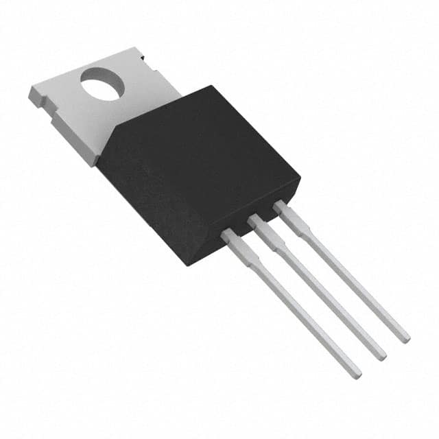
- Package: TO-220
- Essence: Amplification and switching of electronic signals
- Packaging/Quantity: Typically available in reels or tubes containing multiple units
Specifications
- Voltage Rating: 400V
- Current Rating: 4A
- Power Dissipation: 40W
- Gain (hFE): 25-100
- Frequency: Up to 2MHz
- Operating Temperature Range: -65°C to 150°C
Detailed Pin Configuration
The MJE13005G typically has three pins: 1. Collector (C): Connects to the positive supply voltage 2. Base (B): Input control terminal 3. Emitter (E): Connects to the ground or negative supply voltage
Functional Features
- High voltage capability allows for use in power supply circuits
- High current capability enables handling of significant loads
- Fast switching speed facilitates efficient signal amplification and switching
Advantages and Disadvantages
Advantages
- Suitable for high-power applications
- Fast switching speed reduces power loss
- Wide operating temperature range
Disadvantages
- Higher cost compared to lower power transistors
- Requires careful heat dissipation management due to power dissipation rating
Working Principles
The MJE13005G operates based on the principle of controlling the flow of current between the collector and emitter terminals using the base terminal. When a small current flows into the base, it allows a larger current to flow from the collector to the emitter, effectively amplifying the input signal.
Detailed Application Field Plans
The MJE13005G finds extensive use in various applications, including: - Switching power supplies - Audio amplifiers - Motor control circuits - Lighting control systems - Voltage regulators
Detailed and Complete Alternative Models
Some alternative models to the MJE13005G include: - MJE13003G - MJE13007G - MJE13009G - TIP3055 - TIP31C
In conclusion, the MJE13005G power transistor offers high voltage and current capabilities, making it suitable for diverse applications in power electronics and amplification circuits.
Word Count: 330
技術ソリューションにおける MJE13005G の適用に関連する 10 件の一般的な質問と回答をリストします。
What is the maximum collector-emitter voltage (VCEO) of MJE13005G?
- The maximum collector-emitter voltage (VCEO) of MJE13005G is 400V.
What is the maximum collector current (IC) of MJE13005G?
- The maximum collector current (IC) of MJE13005G is 4A.
What is the power dissipation (PD) of MJE13005G?
- The power dissipation (PD) of MJE13005G is 50W.
What are the typical applications of MJE13005G?
- MJE13005G is commonly used in high-voltage, high-speed switching applications such as electronic ballasts, switch mode power supplies, and electronic lamp drivers.
What is the typical hFE (DC current gain) of MJE13005G?
- The typical hFE (DC current gain) of MJE13005G is 20-70 at IC = 0.5A.
What is the maximum junction temperature (Tj) of MJE13005G?
- The maximum junction temperature (Tj) of MJE13005G is 150°C.
Is MJE13005G suitable for use in automotive applications?
- No, MJE13005G is not specifically designed for automotive applications.
What are the recommended operating conditions for MJE13005G?
- The recommended operating conditions for MJE13005G include a collector current (IC) of 4A, a collector-emitter voltage (VCE) of 400V, and a maximum power dissipation (PD) of 50W.
Does MJE13005G require a heat sink for proper operation?
- Yes, MJE13005G typically requires a heat sink to dissipate heat and ensure proper operation, especially when operating at high currents or power levels.
Can MJE13005G be used in audio amplifier circuits?
- While MJE13005G is primarily designed for switching applications, it can be used in certain audio amplifier circuits where its characteristics align with the requirements of the specific design.