

MC74LCX257DTR2
Product Overview
- Category: Integrated Circuit (IC)
- Use: Logic Level Translator
- Characteristics: Low Voltage, Quad 2-Input Multiplexer
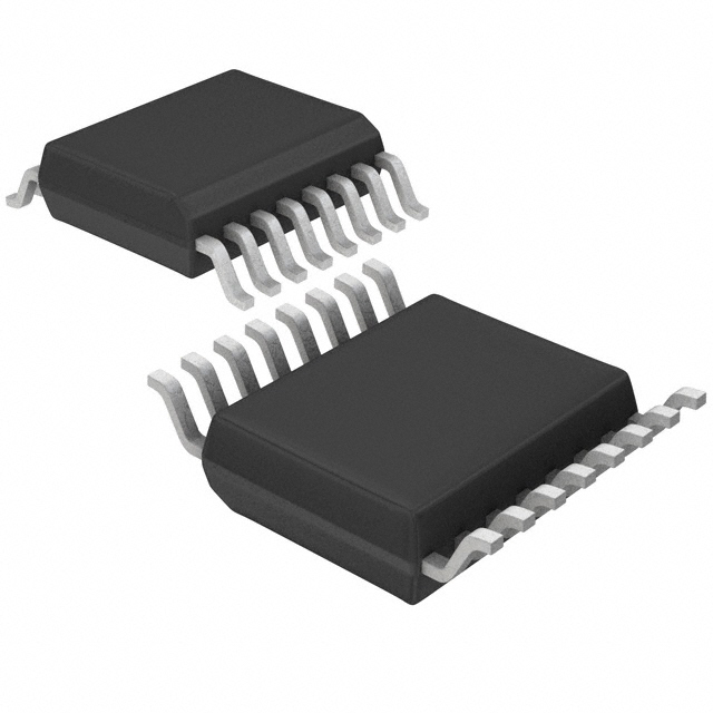
- Package: TSSOP-16
- Essence: The MC74LCX257DTR2 is a logic level translator IC that allows for the translation of signals between different voltage levels. It is specifically designed for low voltage applications.
- Packaging/Quantity: The MC74LCX257DTR2 is available in tape and reel packaging with 2500 units per reel.
Specifications
- Logic Family: LCX
- Number of Inputs: 2
- Number of Outputs: 1
- Voltage - Supply: 2 V ~ 3.6 V
- Operating Temperature: -40°C ~ 85°C
- Propagation Delay: 4.5 ns
- Output Type: Tri-State
- Mounting Type: Surface Mount
- Package / Case: 16-TSSOP (0.173", 4.40mm Width)
Detailed Pin Configuration
The MC74LCX257DTR2 has a total of 16 pins arranged as follows:
+---+--+---+
   A1 -|1  +--+ 16|- VCC
   B1 -|2         |- Y1
   A2 -|3         |- Y2
   B2 -|4         |- GND
   E1 -|5         |- Y3
   E2 -|6         |- Y4
   Y4 -|7         |- E2
   Y3 -|8         |- E1
   GND-|9         |- B2
   Y2 -|10        |- A2
   Y1 -|11        |- B1
 VCC -|12        |- A1
  NC -|13        |- NC
  NC -|14        |- NC
  NC -|15        |- NC
       +---+--+---+
Functional Features
- The MC74LCX257DTR2 is a quad 2-input multiplexer that allows for the selection of one of four input signals to be routed to a single output.
- It operates at low voltage levels, making it suitable for use in battery-powered devices and other low-power applications.
- The tri-state outputs allow for easy connection to other devices without causing any interference.
Advantages and Disadvantages
Advantages
- Low voltage operation extends battery life in portable devices.
- Small package size saves board space.
- Tri-state outputs provide flexibility in signal routing.
Disadvantages
- Limited number of inputs and outputs may not meet the requirements of complex systems.
- Propagation delay of 4.5 ns may introduce timing issues in high-speed applications.
Working Principles
The MC74LCX257DTR2 works by using its control inputs (A1, A2, B1, B2) to select one of the four input signals (E1, E2) to be passed through to the corresponding output (Y1, Y2, Y3, Y4). The selected output is determined by the logic levels applied to the control inputs.
Detailed Application Field Plans
The MC74LCX257DTR2 can be used in various applications where voltage level translation is required. Some potential application fields include:
- Battery-powered devices: The low voltage operation of the MC74LCX257DTR2 makes it suitable for use in portable electronics such as smartphones, tablets, and wearable devices.
- Industrial automation: The IC can be used in control systems that require signal translation between different voltage levels.
- Automotive electronics: The MC74LCX257DTR2 can be utilized in automotive applications where voltage level compatibility is necessary.
Detailed and Complete Alternative Models
- SN74LVC257A: This logic level translator IC offers similar functionality to the MC74LCX257DTR2 and is available in various package options.
- 74HC257: This high-speed CMOS logic level translator provides faster propagation delay but operates at a higher voltage range.
(Note: The above alternative models are provided for reference purposes only. It is recommended to consult the manufacturer's datasheets for detailed specifications and suitability for specific applications.)
Word count: 529 words
技術ソリューションにおける MC74LCX257DTR2 の適用に関連する 10 件の一般的な質問と回答をリストします。
Sure! Here are 10 common questions and answers related to the application of MC74LCX257DTR2 in technical solutions:
Q: What is MC74LCX257DTR2? A: MC74LCX257DTR2 is a quad 2-input multiplexer with 3-state outputs, commonly used in digital logic circuits.
Q: What is the operating voltage range for MC74LCX257DTR2? A: The operating voltage range for MC74LCX257DTR2 is typically between 2.0V and 3.6V.
Q: How many inputs does MC74LCX257DTR2 have? A: MC74LCX257DTR2 has four inputs, labeled A0, A1, A2, and A3.
Q: Can MC74LCX257DTR2 handle both analog and digital signals? A: No, MC74LCX257DTR2 is designed to handle digital signals only.
Q: What is the purpose of the 3-state outputs in MC74LCX257DTR2? A: The 3-state outputs allow multiple MC74LCX257DTR2 devices to be connected together without causing conflicts on the shared output lines.
Q: What is the maximum frequency at which MC74LCX257DTR2 can operate? A: MC74LCX257DTR2 can typically operate at frequencies up to 100MHz.
Q: Can MC74LCX257DTR2 be used as a demultiplexer? A: No, MC74LCX257DTR2 is specifically designed as a multiplexer and cannot be used as a demultiplexer.
Q: What is the power supply current for MC74LCX257DTR2? A: The power supply current for MC74LCX257DTR2 is typically around 4mA.
Q: Can MC74LCX257DTR2 be used in automotive applications? A: Yes, MC74LCX257DTR2 is qualified for automotive applications and can operate within the specified temperature range.
Q: Are there any specific layout considerations when using MC74LCX257DTR2? A: Yes, it is recommended to follow the layout guidelines provided in the datasheet to ensure proper performance and minimize noise coupling.
Please note that these answers are general and may vary depending on the specific application and requirements. It is always recommended to refer to the datasheet and consult with the manufacturer for detailed information.