

MC74AC132DR2G
Basic Information Overview
- Category: Integrated Circuit (IC)
- Use: Logic Gate
- Characteristics: Quad 2-Input NAND Schmitt Trigger
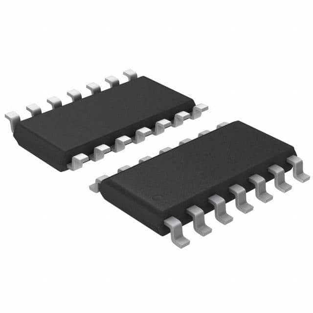
- Package: SOIC-14
- Essence: High-performance digital logic gate
- Packaging/Quantity: Tape and Reel, 2500 units per reel
Specifications
- Supply Voltage Range: 2.0V to 6.0V
- Input Voltage Range: -0.5V to VCC + 0.5V
- Output Voltage Range: 0V to VCC
- Operating Temperature Range: -40°C to +85°C
- Propagation Delay Time: 7ns (typical)
- Maximum Quiescent Current: 4µA at 5.5V
Detailed Pin Configuration
The MC74AC132DR2G has a total of 14 pins arranged as follows:
__    __
   1 | 1  14 | VCC
   2 | 2  13 | A
   3 | 3  12 | B
   4 | 4  11 | C
   5 | 5  10 | D
 GND | 6   9 | Y
   7 | 7   8 | NC
       ‾‾    ‾‾
Functional Features
- Quad 2-Input NAND Schmitt Trigger with Schmitt-trigger inputs
- Provides hysteresis for improved noise immunity
- High-speed operation with low power consumption
- Compatible with TTL and CMOS logic levels
- Wide operating voltage range allows for versatile applications
Advantages and Disadvantages
Advantages: - Improved noise immunity due to Schmitt-trigger inputs - High-speed operation enables efficient digital signal processing - Wide operating voltage range allows for compatibility with various systems
Disadvantages: - Limited number of inputs and outputs (quad 2-input NAND gate) - Not suitable for applications requiring complex logic functions
Working Principles
The MC74AC132DR2G is a quad 2-input NAND Schmitt Trigger. It operates by taking two input signals, A and B, and producing an inverted output signal, Y. The Schmitt-trigger inputs provide hysteresis, which helps in reducing the effects of noise and ensuring stable output transitions. The gate can be powered by a supply voltage ranging from 2.0V to 6.0V.
Detailed Application Field Plans
The MC74AC132DR2G finds applications in various fields, including: 1. Digital electronics: Used in logic circuits, microcontrollers, and digital signal processors. 2. Communication systems: Employed in data transmission and reception circuits. 3. Industrial automation: Utilized in control systems and programmable logic controllers (PLCs). 4. Automotive electronics: Integrated into vehicle control units and electronic control modules. 5. Consumer electronics: Incorporated in devices such as televisions, computers, and smartphones.
Detailed and Complete Alternative Models
- SN74AC132: Similar quad 2-input NAND Schmitt Trigger IC manufactured by Texas Instruments.
- CD4011B: Quad 2-input NAND gate IC produced by ON Semiconductor.
- 74HC132: Quad 2-input NAND gate IC manufactured by NXP Semiconductors.
(Note: This list is not exhaustive and there are several other alternative models available in the market.)
This entry provides an overview of the MC74AC132DR2G, a quad 2-input NAND Schmitt Trigger IC. It includes basic information, specifications, pin configuration, functional features, advantages and disadvantages, working principles, application field plans, and alternative models. The MC74AC132DR2G is a versatile logic gate suitable for various digital electronics applications.
技術ソリューションにおける MC74AC132DR2G の適用に関連する 10 件の一般的な質問と回答をリストします。
Sure! Here are 10 common questions and answers related to the application of MC74AC132DR2G in technical solutions:
Q: What is MC74AC132DR2G? A: MC74AC132DR2G is a quad 2-input NAND gate integrated circuit (IC) that can be used in various digital logic applications.
Q: What is the operating voltage range for MC74AC132DR2G? A: The operating voltage range for MC74AC132DR2G is typically between 2.0V and 6.0V.
Q: Can MC74AC132DR2G be used in high-speed applications? A: Yes, MC74AC132DR2G is designed for high-speed operation and can be used in applications where fast switching times are required.
Q: What is the maximum output current of MC74AC132DR2G? A: The maximum output current of MC74AC132DR2G is typically around 24mA.
Q: Can MC74AC132DR2G be used in both CMOS and TTL logic systems? A: Yes, MC74AC132DR2G is compatible with both CMOS and TTL logic levels, making it versatile for different system designs.
Q: Does MC74AC132DR2G have built-in protection against electrostatic discharge (ESD)? A: Yes, MC74AC132DR2G has built-in ESD protection, which helps safeguard the IC from damage during handling and assembly.
Q: What is the typical propagation delay of MC74AC132DR2G? A: The typical propagation delay of MC74AC132DR2G is around 5 nanoseconds (ns).
Q: Can MC74AC132DR2G be used in battery-powered applications? A: Yes, MC74AC132DR2G can operate within a wide voltage range, making it suitable for battery-powered applications.
Q: Is MC74AC132DR2G available in different package options? A: Yes, MC74AC132DR2G is available in various package options, such as SOIC, TSSOP, and PDIP, providing flexibility for different PCB layouts.
Q: Are there any specific application notes or reference designs available for MC74AC132DR2G? A: Yes, the manufacturer of MC74AC132DR2G provides application notes and reference designs that can help users understand and implement the IC effectively in their technical solutions.
Please note that the answers provided here are general and may vary depending on the specific datasheet and manufacturer's documentation for MC74AC132DR2G.