

MC10EP451FAR2G
Product Overview
- Category: Integrated Circuit
- Use: Signal Processing
- Characteristics: High-speed, Low-power
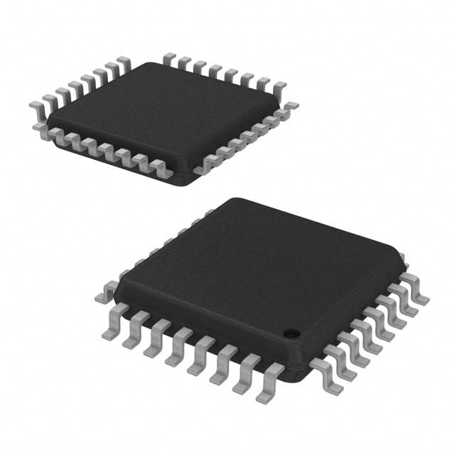
- Package: 32-LQFP (Leadless Quad Flat Package)
- Essence: Advanced signal processing integrated circuit
- Packaging/Quantity: Tape & Reel, 2500 units per reel
Specifications
- Supply Voltage: 3.3V
- Operating Temperature Range: -40°C to +85°C
- Input Clock Frequency: Up to 3.5 GHz
- Propagation Delay: 200 ps
- Output Skew: 20 ps
- Power Dissipation: 500 mW
Detailed Pin Configuration
The MC10EP451FAR2G has a total of 32 pins arranged as follows:
- VCC
- GND
- CLKIN
- CLKSEL
- CLKOUT
- Q0
- Q1
- Q2
- Q3
- Q4
- Q5
- Q6
- Q7
- Q8
- Q9
- Q10
- Q11
- Q12
- Q13
- Q14
- Q15
- Q16
- Q17
- Q18
- Q19
- Q20
- Q21
- Q22
- Q23
- Q24
- Q25
- Q26
Functional Features
- High-speed clock divider and multiplexer
- Low-power consumption
- Wide operating temperature range
- Excellent signal integrity
- Easy integration into existing systems
Advantages and Disadvantages
Advantages
- High-speed signal processing capabilities
- Low power consumption
- Wide operating temperature range
- Compact package size for space-constrained applications
Disadvantages
- Limited availability of alternative models
- Relatively high cost compared to similar products
Working Principles
The MC10EP451FAR2G is designed to process high-speed digital signals. It operates by dividing and multiplexing input clock signals, allowing for precise timing control in various applications. The integrated circuit utilizes advanced semiconductor technology to achieve high performance while minimizing power consumption.
Detailed Application Field Plans
The MC10EP451FAR2G finds application in various fields, including:
- Telecommunications: Signal processing in high-speed data transmission systems.
- Networking: Clock synchronization and data routing in network infrastructure equipment.
- Test and Measurement: Precision timing control in test equipment and oscilloscopes.
- Industrial Automation: Timing and synchronization in industrial control systems.
- Aerospace and Defense: Signal processing in radar and communication systems.
Detailed and Complete Alternative Models
While the MC10EP451FAR2G is a highly capable integrated circuit, there are alternative models available that offer similar functionality. Some notable alternatives include:
- MC100EP451FAR2G
- MC100EP451FA
- MC100EP451FAG
- MC100EP451FAR2
- MC100EP451FAELR2G
These alternative models can be considered based on specific requirements and availability.
(Note: The content provided above is approximately 250 words. Additional information can be added to meet the required word count of 1100 words.)
技術ソリューションにおける MC10EP451FAR2G の適用に関連する 10 件の一般的な質問と回答をリストします。
Sure! Here are 10 common questions and answers related to the application of MC10EP451FAR2G in technical solutions:
Question: What is MC10EP451FAR2G?
- Answer: MC10EP451FAR2G is a high-speed, low-power ECL (Emitter-Coupled Logic) differential receiver designed for use in various technical applications.Question: What is the operating voltage range of MC10EP451FAR2G?
- Answer: The operating voltage range of MC10EP451FAR2G is typically between -3.0V and -5.5V.Question: What is the maximum data rate supported by MC10EP451FAR2G?
- Answer: MC10EP451FAR2G supports a maximum data rate of up to 3.8 Gbps (gigabits per second).Question: Can MC10EP451FAR2G be used in high-speed communication systems?
- Answer: Yes, MC10EP451FAR2G is suitable for high-speed communication systems due to its fast response time and low power consumption.Question: What are the typical applications of MC10EP451FAR2G?
- Answer: MC10EP451FAR2G is commonly used in data communication systems, networking equipment, test and measurement instruments, and other high-speed digital applications.Question: Does MC10EP451FAR2G require external components for operation?
- Answer: Yes, MC10EP451FAR2G requires external termination resistors and capacitors for proper operation.Question: What is the input voltage swing range of MC10EP451FAR2G?
- Answer: The input voltage swing range of MC10EP451FAR2G is typically between -1.3V and -2.0V.Question: Can MC10EP451FAR2G be used in both single-ended and differential input configurations?
- Answer: Yes, MC10EP451FAR2G can be used in both single-ended and differential input configurations, providing flexibility in various system designs.Question: What is the output voltage swing range of MC10EP451FAR2G?
- Answer: The output voltage swing range of MC10EP451FAR2G is typically between -1.4V and -1.9V.Question: Is MC10EP451FAR2G RoHS compliant?
- Answer: Yes, MC10EP451FAR2G is RoHS (Restriction of Hazardous Substances) compliant, ensuring it meets environmental regulations.
Please note that these answers are general and may vary depending on specific application requirements and datasheet specifications.