

MC100EP40DTR2
Overview
Category: Integrated Circuit (IC)
Use: Signal Converter/Driver
Characteristics: - High-speed signal conversion and driving - Compatible with ECL (Emitter-Coupled Logic) logic levels - Low power consumption - Wide operating voltage range - Small form factor
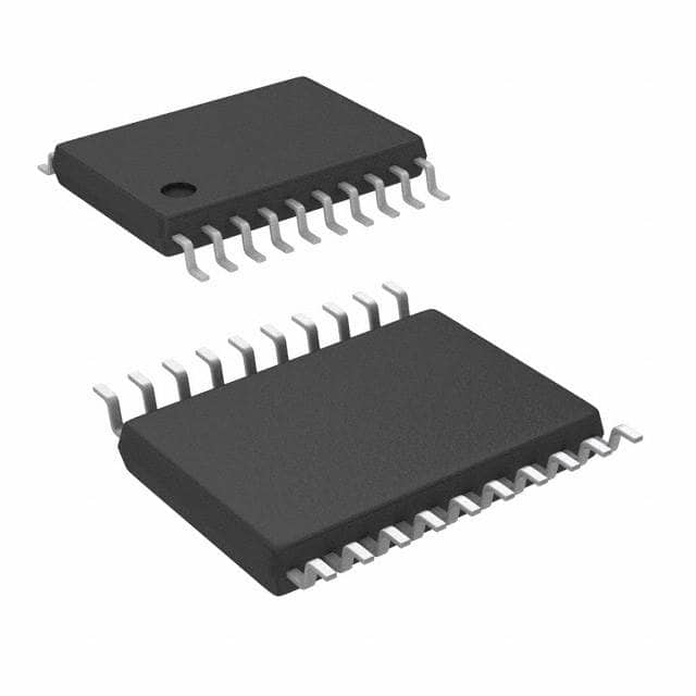
Package: TSSOP-8 (Thin Shrink Small Outline Package)
Essence: MC100EP40DTR2 is a high-speed signal converter/driver IC designed for use in electronic circuits that require fast signal conversion and driving capabilities.
Packaging/Quantity: The MC100EP40DTR2 is typically sold in reels or tubes, with each reel/tube containing a specific quantity of ICs. Please refer to the manufacturer's specifications for detailed packaging and quantity information.
Specifications and Parameters
- Supply Voltage Range: 2.375V to 3.8V
- Input Voltage Range: -2.0V to VCC + 2.0V
- Output Voltage Range: -2.0V to VCC + 2.0V
- Operating Temperature Range: -40°C to +85°C
- Maximum Clock Frequency: 3.5 GHz
- Propagation Delay: 250 ps (typical)
- Output Current: ±50 mA
Pin Configuration
The MC100EP40DTR2 IC has a total of 8 pins arranged as follows:
Pin 1: GND
   Pin 2: Qn Output
   Pin 3: Dn Input
   Pin 4: VCC
   Pin 5: Q Output
   Pin 6: D Input
   Pin 7: /Q Output
   Pin 8: /D Input
Functional Characteristics
The MC100EP40DTR2 is designed to convert and drive high-speed signals. It operates with ECL logic levels, providing fast and reliable signal conversion. The IC features differential inputs and outputs, allowing for noise immunity and improved signal integrity.
Advantages and Disadvantages
Advantages: - High-speed signal conversion and driving capabilities - Wide operating voltage range - Low power consumption - Small form factor
Disadvantages: - Requires knowledge of ECL logic levels for proper use - Limited availability in certain markets
Applicable Range of Products
The MC100EP40DTR2 is commonly used in electronic circuits that require high-speed signal conversion and driving. It finds applications in various industries, including telecommunications, data communication, and computer systems.
Working Principles
The MC100EP40DTR2 operates based on the principles of ECL logic. It receives differential input signals and converts them into compatible output signals with high-speed and low propagation delay. The IC's internal circuitry ensures accurate signal conversion and driving capabilities.
Detailed Application Field Plans
The MC100EP40DTR2 can be used in the following application fields: 1. High-speed data transmission systems 2. Clock distribution networks 3. Fiber optic communication systems 4. Test and measurement equipment 5. Radar and sonar systems
Detailed Alternative Models
Some alternative models to the MC100EP40DTR2 include: - MC100EP40DTG - MC100EP40D - MC100EP40DR2G - MC100EP40DG - MC100EP40DTR2G
Please note that the availability and specifications of alternative models may vary.
5 Common Technical Questions and Answers
Q: What is the maximum clock frequency supported by the MC100EP40DTR2? A: The maximum clock frequency supported by the MC100EP40DTR2 is 3.5 GHz.
Q: Can the MC100EP40DTR2 operate with a supply voltage below 2.375V? A: No, the MC100EP40DTR2 requires a supply voltage within the range of 2.375V to 3.8V for proper operation.
Q: What is the typical propagation delay of the MC100EP40DTR2? A: The typical propagation delay of the MC100EP40DTR2 is 250 ps.
Q: Is the MC100EP40DTR2 compatible with TTL (Transistor-Transistor Logic) logic levels? A: No, the MC100EP40DTR2 operates with ECL logic levels and is not directly compatible with TTL logic.
Q: What is the output current capability of the MC100EP40DTR2? A: The MC100EP40DTR2 can provide an output current of ±50 mA.
This concludes the encyclopedia entry for the MC100EP40D