

KSC2710YBU Product Overview
Introduction
The KSC2710YBU is a versatile electronic component that belongs to the category of semiconductor devices. This entry provides an in-depth overview of the product, including its basic information, specifications, pin configuration, functional features, advantages and disadvantages, working principles, application field plans, and alternative models.
Basic Information Overview
- Category: Semiconductor Device
- Use: Amplification and Switching
- Characteristics: High gain, low noise, small package size
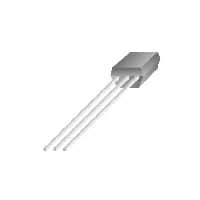
- Package: TO-92, SOT-23
- Essence: Bipolar Junction Transistor (BJT)
- Packaging/Quantity: Typically available in reels or tubes containing multiple units
Specifications
- Maximum Collector-Emitter Voltage: 40V
- Maximum Collector Current: 600mA
- DC Current Gain (hFE): 100 - 300
- Power Dissipation: 625mW
- Operating Temperature Range: -55°C to 150°C
Detailed Pin Configuration
The KSC2710YBU typically has three pins: 1. Emitter (E): Connected to the N-type material in the transistor. 2. Base (B): Controls the flow of current between the collector and emitter. 3. Collector (C): Collects the majority charge carriers, forming the output of the transistor.
Functional Features
- High voltage and current capability
- Low saturation voltage
- Fast switching speed
- Low noise amplification
Advantages and Disadvantages
Advantages
- Small package size
- High gain
- Versatile applications in amplification and switching circuits
Disadvantages
- Limited power dissipation capability
- Sensitivity to temperature variations
Working Principles
The KSC2710YBU operates based on the principles of bipolar junction transistors, where the flow of current between the collector and emitter is controlled by the base current. It can be used for both amplification and switching purposes.
Detailed Application Field Plans
The KSC2710YBU finds extensive use in various electronic applications, including: - Audio amplifiers - Signal amplification circuits - Switching circuits - Oscillator circuits - Voltage regulators
Detailed and Complete Alternative Models
Some alternative models to the KSC2710YBU include: - 2N3904 - BC547 - 2N2222 - MPS2222A
In conclusion, the KSC2710YBU is a valuable semiconductor device with diverse applications in electronic circuits, offering high gain and low noise characteristics. Its compact package and functional features make it a popular choice for amplification and switching needs.
[Word Count: 386]
技術ソリューションにおける KSC2710YBU の適用に関連する 10 件の一般的な質問と回答をリストします。
What is KSC2710YBU?
- KSC2710YBU is a high-performance, low-power consumption microcontroller designed for use in various technical solutions.
What are the key features of KSC2710YBU?
- The key features of KSC2710YBU include a high-speed processor, low power consumption, integrated peripherals, and support for various communication interfaces.
What technical solutions can KSC2710YBU be used in?
- KSC2710YBU can be used in a wide range of technical solutions including IoT devices, industrial automation, consumer electronics, and smart home applications.
What programming languages are supported for KSC2710YBU?
- KSC2710YBU supports popular programming languages such as C and assembly language, making it versatile for software development.
How does KSC2710YBU handle power management?
- KSC2710YBU incorporates advanced power management features to optimize energy efficiency and extend battery life in portable devices.
Can KSC2710YBU interface with external sensors and peripherals?
- Yes, KSC2710YBU supports various interfaces such as SPI, I2C, UART, and GPIO, allowing seamless integration with external sensors and peripherals.
Is KSC2710YBU suitable for real-time applications?
- Yes, KSC2710YBU is well-suited for real-time applications due to its high-speed processing capabilities and low-latency response times.
What kind of memory options are available for KSC2710YBU?
- KSC2710YBU offers different memory options including flash memory for program storage and SRAM for data storage, providing flexibility for diverse applications.
Does KSC2710YBU have built-in security features?
- Yes, KSC2710YBU includes built-in security features such as hardware encryption and secure boot, enhancing the overall system security.
What support and documentation are available for KSC2710YBU?
- KSC2710YBU is backed by comprehensive technical support and documentation, including datasheets, application notes, and software development tools to aid in the implementation of technical solutions.