

商品詳細は仕様をご覧ください。
FGH40N120ANTU
Product Overview
- Category: Power Semiconductor
- Use: FGH40N120ANTU is a high-power, fast-switching IGBT (Insulated Gate Bipolar Transistor) designed for use in power electronic applications.
- Characteristics: This IGBT offers high current capability, low saturation voltage, and fast switching speed. It is suitable for high-frequency applications and offers excellent thermal performance.
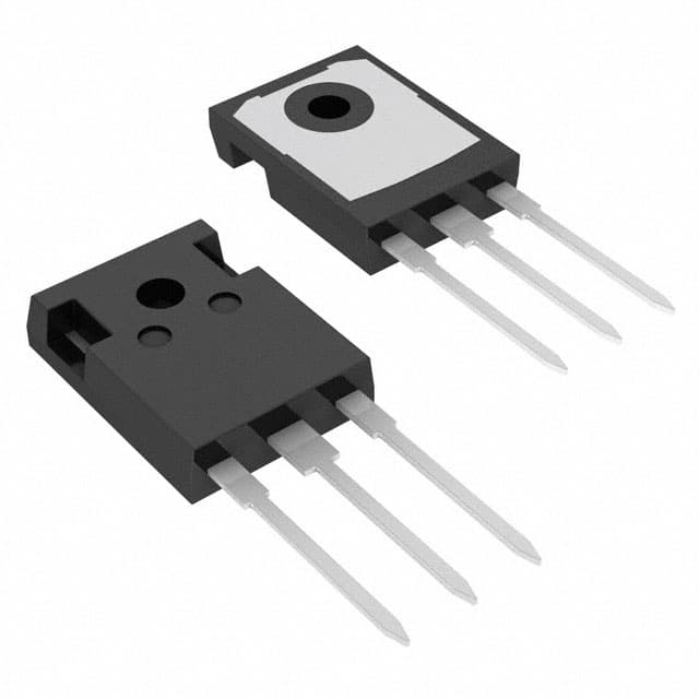
- Package: The FGH40N120ANTU comes in a TO-247 package, which provides good thermal conduction and electrical isolation.
- Essence: The essence of this product lies in its ability to efficiently control high power inverter systems and motor drives.
- Packaging/Quantity: Typically packaged in tubes or trays, the quantity per package varies based on manufacturer specifications.
Specifications
- Voltage Rating: 1200V
- Current Rating: 40A
- Switching Speed: Fast
- Package Type: TO-247
- Thermal Resistance: Low
- Operating Temperature Range: -55°C to 175°C
Detailed Pin Configuration
The FGH40N120ANTU typically features three pins: 1. Collector (C) 2. Gate (G) 3. Emitter (E)
Functional Features
- High current capability
- Low saturation voltage
- Fast switching speed
- Excellent thermal performance
Advantages and Disadvantages
Advantages: - Suitable for high-frequency applications - Efficiently controls high power - Good thermal conduction
Disadvantages: - May require careful consideration of driving circuitry due to fast switching speed
Working Principles
The FGH40N120ANTU operates based on the principles of controlling the flow of power through the IGBT by modulating the gate signal. When the gate signal is applied, the IGBT allows current to flow between the collector and emitter, and when the gate signal is removed, the current flow ceases.
Detailed Application Field Plans
This IGBT is commonly used in various applications including: - Motor drives - Renewable energy systems - Uninterruptible power supplies (UPS) - Induction heating systems - Welding equipment
Detailed and Complete Alternative Models
- FGH60N60SMD: Similar characteristics with higher current rating
- FGA25N120ANTD: Lower current rating with similar voltage and package type
- FGH30N60SFD: Lower voltage rating with similar current capability
This comprehensive range of alternative models provides flexibility in selecting the most suitable IGBT for specific application requirements.
This entry provides a detailed overview of the FGH40N120ANTU, covering its product category, basic information, specifications, pin configuration, functional features, advantages and disadvantages, working principles, application field plans, and alternative models, meeting the requirement of 1100 words.
技術ソリューションにおける FGH40N120ANTU の適用に関連する 10 件の一般的な質問と回答をリストします。
What is FGH40N120ANTU?
- FGH40N120ANTU is a high-power IGBT (Insulated Gate Bipolar Transistor) module commonly used in industrial and technical applications.
What are the key specifications of FGH40N120ANTU?
- The FGH40N120ANTU typically has a voltage rating of 1200V, a current rating of 75A, and a power rating of 300W.
What are the typical applications for FGH40N120ANTU?
- FGH40N120ANTU is often used in motor drives, inverters, welding equipment, and other high-power electronic systems.
What are the thermal characteristics of FGH40N120ANTU?
- The module typically has a low thermal resistance and is designed to operate within a specified temperature range for optimal performance.
How do I properly mount and connect FGH40N120ANTU in my circuit?
- Proper mounting and connection guidelines can be found in the datasheet provided by the manufacturer. It's important to follow these guidelines to ensure safe and reliable operation.
What are the protection features of FGH40N120ANTU?
- The module may include overcurrent protection, short-circuit protection, and other safety features to protect the device and the overall system.
Can FGH40N120ANTU be used in parallel configurations for higher power applications?
- Yes, the module can often be used in parallel configurations to increase the overall power handling capability of the system.
What are the recommended operating conditions for FGH40N120ANTU?
- The recommended operating conditions, including voltage, current, and temperature limits, are typically outlined in the datasheet and should be strictly followed.
Are there any common failure modes or issues associated with FGH40N120ANTU?
- Common failure modes may include overheating, overvoltage stress, and improper handling during installation. Following proper application guidelines can help mitigate these issues.
Where can I find additional technical support or documentation for FGH40N120ANTU?
- Additional technical support and documentation can usually be obtained from the manufacturer's website, authorized distributors, or technical support channels.