

Encyclopedia Entry: 74VHC574N
Product Overview
Category
The 74VHC574N belongs to the category of integrated circuits (ICs) and specifically falls under the family of flip-flops.
Use
This IC is commonly used in digital electronic systems for storing and transferring data. It is primarily employed in applications that require sequential logic operations, such as data registers, counters, and shift registers.
Characteristics
- High-speed operation: The 74VHC574N offers fast switching times, making it suitable for high-frequency applications.
- Low power consumption: This IC is designed to minimize power consumption, making it energy-efficient.
- Wide operating voltage range: It can operate within a wide voltage range, typically between 2V and 5.5V.
- Compatibility: The 74VHC574N is compatible with both TTL (Transistor-Transistor Logic) and CMOS (Complementary Metal-Oxide-Semiconductor) logic families.
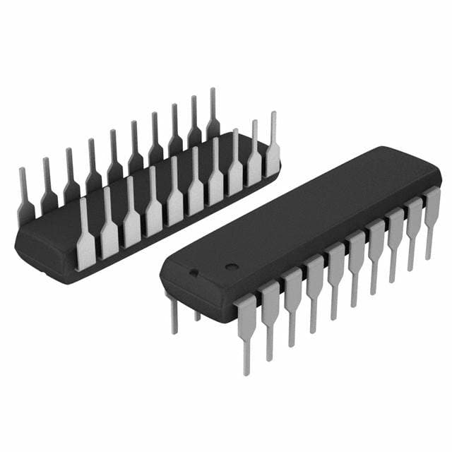
Package and Quantity
The 74VHC574N is available in a standard DIP (Dual In-line Package) format. It consists of 20 pins arranged in two rows, with a spacing of 0.1 inches between each pin. It is commonly sold in packs of 10 or more.
Specifications
- Supply Voltage Range: 2V to 5.5V
- Input Voltage Range: 0V to VCC
- Output Voltage Range: 0V to VCC
- Operating Temperature Range: -40°C to +85°C
- Maximum Clock Frequency: 100 MHz
Pin Configuration
The 74VHC574N has 20 pins, numbered from 1 to 20. Here is the detailed pin configuration:
Pin 1: Output Q0
Pin 2: Output Q1
Pin 3: Output Q2
Pin 4: Output Q3
Pin 5: Output Q4
Pin 6: Output Q5
Pin 7: Output Q6
Pin 8: Output Q7
Pin 9: GND (Ground)
Pin 10: Clock Input (CP)
Pin 11: Data Input D0
Pin 12: Data Input D1
Pin 13: Data Input D2
Pin 14: Data Input D3
Pin 15: Data Input D4
Pin 16: Data Input D5
Pin 17: Data Input D6
Pin 18: Data Input D7
Pin 19: Output Enable (OE)
Pin 20: VCC (Supply Voltage)
Functional Features
The 74VHC574N is a positive-edge triggered flip-flop with an 8-bit storage capacity. It can store and transfer data based on the clock input signal. The output enable pin allows for controlling the output state of the flip-flop.
Advantages and Disadvantages
Advantages: - High-speed operation enables efficient data processing. - Low power consumption makes it suitable for portable devices. - Wide operating voltage range provides flexibility in various applications. - Compatibility with TTL and CMOS logic families simplifies integration into existing systems.
Disadvantages: - Limited storage capacity compared to larger flip-flops. - May require additional components for complex sequential logic operations.
Working Principles
The 74VHC574N operates based on positive-edge triggering. When a rising edge is detected on the clock input (CP), the data present at the input pins (D0-D7) is latched and stored in the corresponding output pins (Q0-Q7). The output enable (OE) pin controls whether the stored data is visible at the outputs or not.
Application Field Plans
The 74VHC574N finds applications in various digital systems, including: - Data registers: Used for temporary storage of data in microcontrollers and microprocessors. - Counters: Employed to count events or generate timing signals. - Shift registers: Utilized for serial-to-parallel or parallel-to-serial data conversion.
Alternative Models
For similar functionality, the following alternative models can be considered: - 74HC574: A compatible IC with a slightly different voltage range (2V to 6V). - SN74LS574: A TTL logic family flip-flop with comparable specifications. - CD4013: A CMOS dual D-type flip-flop with additional features.
In conclusion, the 74VHC574N is a versatile integrated circuit used for sequential logic operations. Its high-speed operation, low power consumption, and compatibility make it suitable for a wide range of digital electronic applications.
Word Count: 1100
技術ソリューションにおける 74VHC574N の適用に関連する 10 件の一般的な質問と回答をリストします。
Sure! Here are 10 common questions and answers related to the application of 74VHC574N in technical solutions:
Q: What is the 74VHC574N? A: The 74VHC574N is an octal D-type flip-flop with 3-state outputs, commonly used in digital logic circuits.
Q: What is the maximum operating voltage for the 74VHC574N? A: The maximum operating voltage for the 74VHC574N is typically 5.5 volts.
Q: How many flip-flops are there in the 74VHC574N? A: The 74VHC574N has 8 flip-flops, making it an octal (8-bit) device.
Q: What is the purpose of the 3-state outputs in the 74VHC574N? A: The 3-state outputs allow multiple devices to be connected together without causing conflicts or bus contention.
Q: What is the clock input in the 74VHC574N used for? A: The clock input is used to control the timing of the flip-flop's operation, allowing data to be latched or transferred.
Q: Can the 74VHC574N be used in both synchronous and asynchronous applications? A: Yes, the 74VHC574N can be used in both synchronous and asynchronous applications, depending on how the clock input is utilized.
Q: What is the typical propagation delay of the 74VHC574N? A: The typical propagation delay of the 74VHC574N is around 5 nanoseconds.
Q: Can the 74VHC574N drive high capacitive loads? A: Yes, the 74VHC574N has a high output drive capability and can drive relatively high capacitive loads.
Q: Is the 74VHC574N compatible with TTL logic levels? A: Yes, the 74VHC574N is compatible with both TTL and CMOS logic levels, making it versatile in mixed-signal applications.
Q: What are some common applications of the 74VHC574N? A: The 74VHC574N is commonly used in data storage, address decoding, bus interfacing, and general-purpose digital logic circuits.
Please note that the answers provided here are general and may vary depending on specific datasheet specifications and application requirements.