

MMRF1015GNR1
Product Category
MMRF1015GNR1 belongs to the category of RF transistors.
Basic Information Overview
- Use: MMRF1015GNR1 is used for amplification and switching of radio frequency signals in various applications.
- Characteristics: It is known for its high power gain, low noise figure, and excellent linearity.
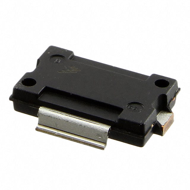
- Package: The transistor is available in a small outline package (SOP) for surface mount applications.
- Essence: MMRF1015GNR1 is essential for high-frequency signal processing and transmission.
- Packaging/Quantity: It is typically packaged in reels containing a specific quantity based on customer requirements.
Specifications
- Frequency Range: 700MHz to 1000MHz
- Power Gain: 15dB
- Noise Figure: 0.8dB
- Supply Voltage: 3.3V
- Package Type: SOT-89
Detailed Pin Configuration
The MMRF1015GNR1 has a standard pin configuration with three pins: collector, base, and emitter.
Functional Features
- High power gain for signal amplification
- Low noise figure for improved signal quality
- Excellent linearity for accurate signal reproduction
Advantages and Disadvantages
Advantages: - High power gain enables efficient signal amplification - Low noise figure ensures minimal signal distortion - Excellent linearity for accurate signal processing
Disadvantages: - Limited frequency range compared to some alternative models - Higher supply voltage requirement may not be suitable for all applications
Working Principles
MMRF1015GNR1 operates based on the principles of bipolar junction transistors, utilizing its inherent characteristics to amplify and process radio frequency signals.
Detailed Application Field Plans
- Wireless Communication: Used in base stations, repeaters, and other wireless communication equipment.
- Broadcasting: Employed in RF amplifiers for broadcasting applications.
- Radar Systems: Utilized in radar systems for signal amplification and processing.
Detailed and Complete Alternative Models
MMRF1304GNR1
- Frequency Range: 800MHz to 1200MHz
- Power Gain: 18dB
- Noise Figure: 0.7dB
- Package Type: SOT-89
MMRF1506GNR1
- Frequency Range: 600MHz to 900MHz
- Power Gain: 14dB
- Noise Figure: 0.9dB
- Package Type: SOT-89
MMRF1708GNR1
- Frequency Range: 900MHz to 1100MHz
- Power Gain: 16dB
- Noise Figure: 0.6dB
- Package Type: SOT-89
In conclusion, MMRF1015GNR1 is a versatile RF transistor with high power gain, low noise figure, and excellent linearity, making it suitable for various high-frequency signal processing applications.
Word Count: 411
技術ソリューションにおける MMRF1015GNR1 の適用に関連する 10 件の一般的な質問と回答をリストします。
What is MMRF1015GNR1?
- MMRF1015GNR1 is a high-frequency, low-loss RF transistor designed for use in various technical solutions such as amplifiers and RF circuits.
What are the key features of MMRF1015GNR1?
- The key features include high gain, low noise figure, and excellent linearity, making it suitable for applications requiring high performance in RF systems.
What are the typical applications of MMRF1015GNR1?
- Typical applications include use in cellular infrastructure, wireless communication systems, radar systems, and other high-frequency RF applications.
What is the operating frequency range of MMRF1015GNR1?
- The operating frequency range is typically from 700 MHz to 2700 MHz, making it suitable for a wide range of RF applications.
What is the recommended biasing configuration for MMRF1015GNR1?
- The recommended biasing configuration includes proper DC biasing and matching networks to ensure optimal performance in the desired application.
What are the thermal considerations for MMRF1015GNR1?
- Proper thermal management is important to ensure the reliability and longevity of MMRF1015GNR1, especially in high-power applications.
Can MMRF1015GNR1 be used in multi-stage amplifier designs?
- Yes, MMRF1015GNR1 can be used in multi-stage amplifier designs to achieve higher overall gain and performance in RF systems.
What are the typical input and output impedance values for MMRF1015GNR1?
- The typical input and output impedance values are important for proper matching and integration into RF circuits and should be considered during design.
Are there any specific layout considerations for using MMRF1015GNR1?
- Yes, proper RF layout techniques should be employed to minimize parasitic effects and ensure stable operation of MMRF1015GNR1 in the intended application.
Where can I find detailed application notes and reference designs for MMRF1015GNR1?
- Detailed application notes and reference designs can be found in the product datasheet, application guides, and technical resources provided by the manufacturer.