

74HCT534N,652
Product Overview
Category
The 74HCT534N,652 belongs to the category of integrated circuits (ICs).
Use
This IC is commonly used in digital electronics for various applications such as data storage, signal processing, and control systems.
Characteristics
- High-speed operation
- Low power consumption
- Wide operating voltage range
- Compatibility with TTL (Transistor-Transistor Logic) inputs
- Output capability: 4 mA at 5 V
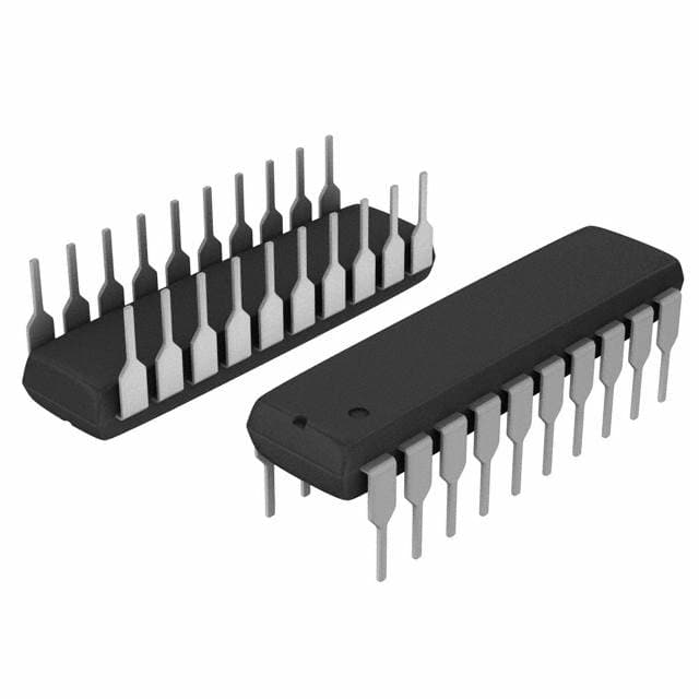
Package
The 74HCT534N,652 is available in a standard DIP (Dual In-line Package) format. It consists of 20 pins arranged in two rows.
Essence
The essence of this IC lies in its ability to store and process digital information efficiently, making it an essential component in modern electronic devices.
Packaging/Quantity
The 74HCT534N,652 is typically packaged in reels or tubes, containing a specific quantity of ICs per package. The exact quantity may vary depending on the manufacturer's specifications.
Specifications
- Supply voltage: 2 V to 6 V
- Input voltage: 0 V to VCC
- Operating temperature range: -40°C to +125°C
- Propagation delay time: 10 ns (max)
- Output current: 4 mA (max)
Detailed Pin Configuration
- GND (Ground)
- D0 (Data Input 0)
- D1 (Data Input 1)
- D2 (Data Input 2)
- D3 (Data Input 3)
- D4 (Data Input 4)
- D5 (Data Input 5)
- D6 (Data Input 6)
- D7 (Data Input 7)
- OE (Output Enable)
- CP (Clock Pulse)
- MR (Master Reset)
- Q0 (Output 0)
- Q1 (Output 1)
- Q2 (Output 2)
- Q3 (Output 3)
- Q4 (Output 4)
- Q5 (Output 5)
- Q6 (Output 6)
- VCC (Supply Voltage)
Functional Features
- Data storage: The IC can store digital information on its inputs and retain it until a new value is received.
- Output control: The output enable (OE) pin allows the user to enable or disable the outputs, providing flexibility in controlling the flow of data.
- Clock synchronization: The clock pulse (CP) pin ensures that the data inputs are sampled at the appropriate time, allowing for synchronized operations.
Advantages and Disadvantages
Advantages
- High-speed operation enables efficient data processing.
- Low power consumption contributes to energy efficiency.
- Wide operating voltage range allows for compatibility with various systems.
- TTL compatibility simplifies integration with existing circuits.
Disadvantages
- Limited output current may restrict certain applications requiring higher current capabilities.
- Propagation delay time may introduce timing constraints in time-critical applications.
Working Principles
The 74HCT534N,652 operates based on the principles of digital logic. It utilizes flip-flops and logic gates to store and process binary information. The clock pulse synchronizes the input data, which is then stored in the flip-flops. The stored data can be accessed through the output pins when enabled by the output enable signal.
Detailed Application Field Plans
The 74HCT534N,652 finds application in various fields, including but not limited to: - Microcontrollers - Data communication systems - Industrial automation - Digital signal processing - Control systems
Detailed and Complete Alternative Models
Some alternative models to the 74HCT534N,652 include: - 74LS534 - CD74HCT534E - SN74HCT534N
These models offer similar functionality and can be used as substitutes depending on specific requirements.
In conclusion, the 74HCT534N,652 is a versatile integrated circuit widely used in digital electronics. Its high-speed operation, low power consumption, and compatibility with TTL inputs make it suitable for various applications. However, its limited output current and propagation delay time should be considered when selecting this IC for specific projects.
技術ソリューションにおける 74HCT534N,652 の適用に関連する 10 件の一般的な質問と回答をリストします。
Sure! Here are 10 common questions and answers related to the application of 74HCT534N,652 in technical solutions:
1. What is the function of the 74HCT534N,652? The 74HCT534N,652 is an octal D-type flip-flop with 3-state outputs. It can store and transfer data in digital circuits.
2. What is the voltage range supported by the 74HCT534N,652? The 74HCT534N,652 supports a voltage range of 4.5V to 5.5V.
3. How many flip-flops are there in the 74HCT534N,652? The 74HCT534N,652 has 8 flip-flops, making it an octal flip-flop.
4. What is the maximum clock frequency supported by the 74HCT534N,652? The maximum clock frequency supported by the 74HCT534N,652 is typically around 80 MHz.
5. Can the 74HCT534N,652 be used for both synchronous and asynchronous applications? Yes, the 74HCT534N,652 can be used for both synchronous and asynchronous applications.
6. What is the output drive capability of the 74HCT534N,652? The 74HCT534N,652 has a high output drive capability, allowing it to drive low impedance loads.
7. Does the 74HCT534N,652 have internal pull-up or pull-down resistors? No, the 74HCT534N,652 does not have internal pull-up or pull-down resistors. External resistors may be required if needed.
8. Can the 74HCT534N,652 be cascaded to increase the number of flip-flops? Yes, the 74HCT534N,652 can be cascaded to increase the number of flip-flops and create larger storage or shift register systems.
9. What is the power supply current consumption of the 74HCT534N,652? The power supply current consumption of the 74HCT534N,652 depends on various factors but typically ranges from a few milliamperes to tens of milliamperes.
10. Are there any specific precautions to consider when using the 74HCT534N,652? Some precautions to consider when using the 74HCT534N,652 include avoiding excessive voltage or current, ensuring proper decoupling capacitors are used, and following the recommended operating conditions mentioned in the datasheet.
Please note that these answers are general and may vary depending on the specific application and requirements. It's always recommended to refer to the datasheet and consult with technical experts for accurate information.