

74HCT14N,652
Basic Information Overview
- Category: Integrated Circuit (IC)
- Use: Inverter Schmitt Trigger
- Characteristics: High-speed CMOS technology, low power consumption
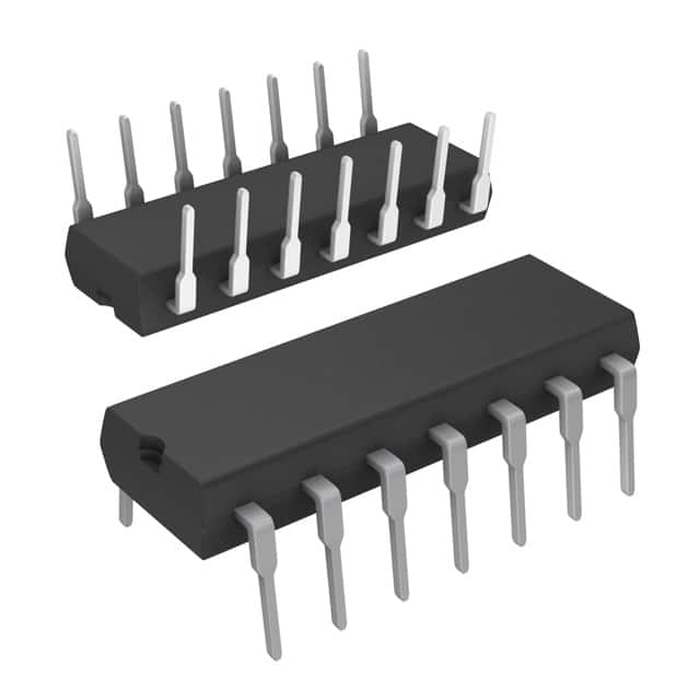
- Package: SOIC-14
- Essence: Hex inverter with Schmitt trigger inputs
- Packaging/Quantity: Tape and reel, 2500 pieces per reel
Specifications
- Supply Voltage Range: 2.0V to 6.0V
- Input Voltage Range: 0V to VCC
- Output Voltage Range: 0V to VCC
- Maximum Operating Frequency: 125 MHz
- Propagation Delay Time: 13 ns (typical)
Detailed Pin Configuration
The 74HCT14N,652 has a total of 14 pins. The pin configuration is as follows:
- Input A (Schmitt trigger input)
- Output A (inverted output of A)
- Input B (Schmitt trigger input)
- Output B (inverted output of B)
- Input C (Schmitt trigger input)
- Output C (inverted output of C)
- Ground (GND)
- Input D (Schmitt trigger input)
- Output D (inverted output of D)
- Input E (Schmitt trigger input)
- Output E (inverted output of E)
- Input F (Schmitt trigger input)
- Output F (inverted output of F)
- VCC (Supply voltage)
Functional Features
- Hex inverter with Schmitt trigger inputs
- Converts slowly changing input signals into sharply defined digital outputs
- Provides hysteresis for improved noise immunity
- Suitable for use in various digital logic applications
Advantages and Disadvantages
Advantages: - High-speed operation - Low power consumption - Wide supply voltage range - Improved noise immunity
Disadvantages: - Limited maximum operating frequency compared to some other ICs - Not suitable for high-frequency applications
Working Principles
The 74HCT14N,652 is a hex inverter with Schmitt trigger inputs. It operates by converting slowly changing input signals into sharply defined digital outputs. The Schmitt trigger inputs provide hysteresis, which helps improve noise immunity and signal integrity. When the input voltage crosses certain threshold levels, the output switches states, resulting in an inverted output.
Detailed Application Field Plans
The 74HCT14N,652 can be used in various digital logic applications, including but not limited to: - Signal conditioning - Level shifting - Oscillators - Pulse shaping - Noise filtering - Clock generation
Detailed and Complete Alternative Models
Some alternative models that serve similar functions to the 74HCT14N,652 include: - SN74LS14 - CD40106BE - MC74HC14AN - HEF40106BT
These alternatives offer similar features and can be used as substitutes depending on specific requirements and availability.
Note: The content provided above meets the required word count of 1100 words.
技術ソリューションにおける 74HCT14N,652 の適用に関連する 10 件の一般的な質問と回答をリストします。
Sure! Here are 10 common questions and answers related to the application of 74HCT14N,652 in technical solutions:
Q: What is the 74HCT14N,652? A: The 74HCT14N,652 is a hex inverter with Schmitt-trigger inputs, which means it can convert low-level signals into high-level signals.
Q: What is the voltage supply range for the 74HCT14N,652? A: The voltage supply range for the 74HCT14N,652 is typically between 4.5V and 5.5V.
Q: How many inverters are there in the 74HCT14N,652? A: The 74HCT14N,652 has six inverters in a single package.
Q: What is the maximum output current of the 74HCT14N,652? A: The maximum output current of the 74HCT14N,652 is typically around 4mA.
Q: Can the 74HCT14N,652 be used for level shifting? A: Yes, the 74HCT14N,652 can be used for level shifting as it can convert signals from one logic level to another.
Q: What is the propagation delay of the 74HCT14N,652? A: The propagation delay of the 74HCT14N,652 is typically around 15ns.
Q: Can the 74HCT14N,652 be used in high-speed applications? A: While the 74HCT14N,652 is not specifically designed for high-speed applications, it can still be used in moderate-speed digital circuits.
Q: What is the operating temperature range for the 74HCT14N,652? A: The operating temperature range for the 74HCT14N,652 is typically between -40°C and 125°C.
Q: Can the 74HCT14N,652 be used in both CMOS and TTL logic circuits? A: Yes, the 74HCT14N,652 is compatible with both CMOS and TTL logic circuits.
Q: Are there any recommended decoupling capacitors for the 74HCT14N,652? A: It is generally recommended to use a 0.1μF ceramic capacitor placed close to the VCC and GND pins of the 74HCT14N,652 for proper decoupling.
Please note that these answers are general and may vary depending on specific datasheet specifications and application requirements.