

74HC4059DB,112
Basic Information Overview
- Category: Integrated Circuit (IC)
- Use: Multiplexer/Demultiplexer
- Characteristics:
- High-speed CMOS technology
- Wide operating voltage range
- Low power consumption
- Schmitt-trigger action on all inputs
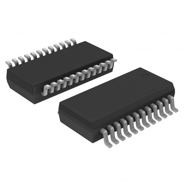
- Package: SSOP-24
- Essence: 8-channel analog multiplexer/demultiplexer
- Packaging/Quantity: Tape and Reel, 2500 pieces per reel
Specifications
- Supply Voltage Range: 2V to 6V
- Input Voltage Range: GND to VCC
- Operating Temperature Range: -40°C to +125°C
- On-state Resistance: 70Ω (typical) at VCC = 4.5V
- Channel-to-Channel Crosstalk: -80dB at f = 1MHz
Detailed Pin Configuration
The 74HC4059DB,112 has a total of 24 pins arranged as follows:
+----\/----+
   A0 | 1      24 | VCC
   A1 | 2      23 | E
   A2 | 3      22 | Y7
   A3 | 4      21 | Y6
   A4 | 5      20 | Y5
   A5 | 6      19 | Y4
   A6 | 7      18 | Y3
   A7 | 8      17 | Y2
  GND | 9      16 | Y1
   S0 | 10     15 | Y0
   S1 | 11     14 | Z
   S2 | 12     13 | GND
       +----------+
Functional Features
- 8-channel multiplexer/demultiplexer
- Wide operating voltage range allows compatibility with various systems
- Low power consumption makes it suitable for battery-powered devices
- Schmitt-trigger action on all inputs ensures noise immunity and hysteresis
Advantages and Disadvantages
Advantages: - High-speed CMOS technology enables fast switching times - Wide operating voltage range provides flexibility in different applications - Low power consumption prolongs battery life - Schmitt-trigger action enhances noise immunity
Disadvantages: - Limited number of channels (8) - May require additional external components for certain applications
Working Principles
The 74HC4059DB,112 is an analog multiplexer/demultiplexer IC that allows the selection of one input from multiple channels. It operates by controlling the S0, S1, and S2 pins to select the desired channel. The selected input is then routed to the output pin (Y) or demultiplexed to the Z pin.
Detailed Application Field Plans
The 74HC4059DB,112 can be used in various applications, including but not limited to: - Data acquisition systems - Communication systems - Audio/video signal routing - Industrial automation - Test and measurement equipment
Detailed and Complete Alternative Models
Some alternative models to the 74HC4059DB,112 include: - CD4051B: 8-channel analog multiplexer/demultiplexer in a DIP package - SN74HC4067: 16-channel analog multiplexer/demultiplexer in a TSSOP package - ADG508F: 8-channel analog multiplexer/demultiplexer with low on-resistance
These alternative models offer similar functionality and can be considered based on specific requirements and availability.
Word count: 346 words
技術ソリューションにおける 74HC4059DB,112 の適用に関連する 10 件の一般的な質問と回答をリストします。
Sure! Here are 10 common questions and answers related to the application of 74HC4059DB,112 in technical solutions:
Q: What is the function of the 74HC4059DB,112? A: The 74HC4059DB,112 is a 4-bit binary up/down counter with asynchronous reset and synchronous load.
Q: What is the maximum clock frequency supported by the 74HC4059DB,112? A: The maximum clock frequency supported by the 74HC4059DB,112 is typically around 25 MHz.
Q: Can the 74HC4059DB,112 be used as a frequency divider? A: Yes, the 74HC4059DB,112 can be used as a frequency divider by connecting the clock input to a higher frequency source and using the outputs accordingly.
Q: How many outputs does the 74HC4059DB,112 have? A: The 74HC4059DB,112 has 4 outputs labeled Q0, Q1, Q2, and Q3.
Q: Can the 74HC4059DB,112 be cascaded to increase the number of bits? A: Yes, multiple 74HC4059DB,112 counters can be cascaded together to increase the number of bits and achieve larger counting ranges.
Q: Does the 74HC4059DB,112 require external power supply decoupling capacitors? A: Yes, it is recommended to use decoupling capacitors (typically 100nF) between VCC and GND pins to stabilize the power supply.
Q: What is the voltage range supported by the 74HC4059DB,112? A: The 74HC4059DB,112 supports a voltage range of 2V to 6V.
Q: Can the 74HC4059DB,112 be used in both up-counting and down-counting modes? A: Yes, the 74HC4059DB,112 can be configured for both up-counting and down-counting by connecting appropriate control inputs.
Q: Does the 74HC4059DB,112 have any built-in error detection or correction features? A: No, the 74HC4059DB,112 does not have any built-in error detection or correction features. It is a basic counter IC.
Q: Are there any specific precautions to consider while using the 74HC4059DB,112? A: It is important to ensure that the voltage levels applied to the inputs are within the specified range (VCC and GND). Additionally, proper decoupling and grounding techniques should be followed for stable operation.
Please note that the answers provided here are general and may vary depending on the specific datasheet and application requirements.