

Encyclopedia Entry: 74ABT651PW,112
Product Information
Category
The 74ABT651PW,112 belongs to the category of integrated circuits (ICs).
Use
This product is commonly used in electronic devices for data transmission and signal processing.
Characteristics
- High-speed operation
- Low power consumption
- Wide operating voltage range
- Compatibility with various logic families
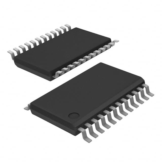
Package
The 74ABT651PW,112 is available in a small outline package (SOP) format.
Essence
This integrated circuit serves as a bus transceiver, facilitating bidirectional data transfer between two buses.
Packaging/Quantity
The 74ABT651PW,112 is typically packaged in reels, with each reel containing a quantity of 2500 units.
Specifications
- Supply Voltage Range: 4.5V to 5.5V
- Operating Temperature Range: -40°C to +85°C
- Input/Output Type: Tri-State
- Number of Channels: 8
- Logic Family: ABT
Detailed Pin Configuration
The 74ABT651PW,112 features the following pin configuration:
- OE (Output Enable)
- A1 (Bus A Data Input/Output)
- A2 (Bus A Data Input/Output)
- A3 (Bus A Data Input/Output)
- A4 (Bus A Data Input/Output)
- A5 (Bus A Data Input/Output)
- A6 (Bus A Data Input/Output)
- A7 (Bus A Data Input/Output)
- GND (Ground)
- B7 (Bus B Data Input/Output)
- B6 (Bus B Data Input/Output)
- B5 (Bus B Data Input/Output)
- B4 (Bus B Data Input/Output)
- B3 (Bus B Data Input/Output)
- B2 (Bus B Data Input/Output)
- B1 (Bus B Data Input/Output)
- VCC (Supply Voltage)
Functional Features
- Bidirectional data transfer between Bus A and Bus B
- Tri-State outputs for bus isolation
- Output enable control for flexible operation
- High-speed operation for efficient data transmission
Advantages and Disadvantages
Advantages
- High-speed operation enables fast data transfer
- Low power consumption for energy-efficient applications
- Wide operating voltage range allows compatibility with various systems
- Tri-State outputs provide bus isolation capability
Disadvantages
- Limited number of channels (8) may not be suitable for applications requiring a higher channel count
- Requires careful consideration of input/output voltage levels to ensure proper functionality
Working Principles
The 74ABT651PW,112 operates based on the principles of digital logic circuits. It utilizes internal circuitry to facilitate bidirectional data transfer between two buses, A and B. The output enable (OE) pin controls the direction of data flow and enables or disables the tri-state outputs.
Detailed Application Field Plans
The 74ABT651PW,112 finds application in various fields, including: - Computer systems - Communication equipment - Industrial automation - Consumer electronics - Automotive electronics
Detailed and Complete Alternative Models
Some alternative models that offer similar functionality to the 74ABT651PW,112 include: - 74HC651 - 74LS651 - SN74ABT651
These alternatives can be considered based on specific requirements and compatibility with existing systems.
In conclusion, the 74ABT651PW,112 is a versatile integrated circuit used for bidirectional data transfer between buses. Its high-speed operation, low power consumption, and wide operating voltage range make it suitable for various applications in different fields.
技術ソリューションにおける 74ABT651PW,112 の適用に関連する 10 件の一般的な質問と回答をリストします。
Sure! Here are 10 common questions and answers related to the application of 74ABT651PW,112 in technical solutions:
Q: What is the function of the 74ABT651PW,112? A: The 74ABT651PW,112 is an octal transceiver with 3-state outputs. It can be used for bidirectional data transfer between buses operating at different voltage levels.
Q: What is the maximum operating voltage for the 74ABT651PW,112? A: The maximum operating voltage for the 74ABT651PW,112 is typically 5.5V.
Q: Can the 74ABT651PW,112 handle level shifting between different voltage domains? A: Yes, the 74ABT651PW,112 is designed to handle level shifting between different voltage domains, making it suitable for interfacing between systems with different voltage requirements.
Q: How many data lines can the 74ABT651PW,112 handle? A: The 74ABT651PW,112 can handle 8 bidirectional data lines.
Q: Does the 74ABT651PW,112 support 3-state outputs? A: Yes, the 74ABT651PW,112 supports 3-state outputs, allowing multiple devices to share a common bus without interfering with each other.
Q: What is the typical propagation delay of the 74ABT651PW,112? A: The typical propagation delay of the 74ABT651PW,112 is around 5 ns.
Q: Can the 74ABT651PW,112 be used in high-speed applications? A: Yes, the 74ABT651PW,112 is designed for high-speed operation and can be used in applications where fast data transfer is required.
Q: Does the 74ABT651PW,112 have built-in ESD protection? A: Yes, the 74ABT651PW,112 typically includes built-in ESD protection to safeguard against electrostatic discharge events.
Q: Can the 74ABT651PW,112 be used in both commercial and industrial environments? A: Yes, the 74ABT651PW,112 is designed to operate reliably in both commercial and industrial temperature ranges.
Q: Are there any specific application notes or reference designs available for the 74ABT651PW,112? A: Yes, the manufacturer of the 74ABT651PW,112 typically provides application notes and reference designs that can help guide the implementation of the device in various technical solutions.