

74HCT164PW,118
Product Overview
- Category: Integrated Circuit (IC)
- Use: Shift Register
- Characteristics: High-speed operation, low power consumption
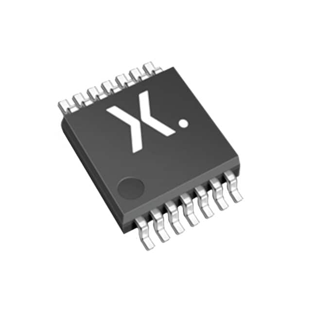
- Package: TSSOP-14
- Essence: Serial-in, parallel-out shift register
- Packaging/Quantity: Tape and reel, 2500 pieces per reel
Specifications
- Logic Family: HCT
- Number of Bits: 8
- Input Voltage: 2V to 6V
- Output Voltage: 0V to VCC
- Operating Temperature Range: -40°C to +125°C
- Propagation Delay: 13 ns (typical)
- Supply Current: 4.5 mA (typical)
Detailed Pin Configuration
- GND (Ground)
- SER (Serial Data Input)
- QA (Parallel Output A)
- QB (Parallel Output B)
- QC (Parallel Output C)
- QD (Parallel Output D)
- QE (Parallel Output E)
- QF (Parallel Output F)
- QG (Parallel Output G)
- QH (Parallel Output H)
- MR (Master Reset)
- CP (Clock Pulse Input)
- DS (Serial Data Input)
- VCC (Supply Voltage)
Functional Features
- Serial-in, parallel-out shifting of data
- Asynchronous master reset
- Positive-edge triggered clock input
- Buffered outputs for driving external loads
- Wide operating voltage range
Advantages and Disadvantages
Advantages: - High-speed operation - Low power consumption - Easy integration into digital circuits - Compact package size
Disadvantages: - Limited number of bits (8 in this case) - Requires an external clock signal
Working Principles
The 74HCT164PW,118 is a serial-in, parallel-out shift register. It allows the user to input data serially and output it in parallel form. The shift register consists of eight flip-flops connected in series, with each flip-flop storing one bit of data. The data is shifted through the flip-flops on each clock pulse, and the parallel outputs reflect the current state of the shift register.
The master reset (MR) input asynchronously clears all the flip-flops to their initial state. The clock pulse (CP) input triggers the shifting of data from the serial input (SER) to the first flip-flop. The serial data is then propagated through the remaining flip-flops on subsequent clock pulses.
Detailed Application Field Plans
The 74HCT164PW,118 can be used in various applications that require serial-to-parallel data conversion. Some potential application fields include:
- LED Matrix Displays: The shift register can be used to control multiple LEDs in a matrix arrangement, allowing for efficient use of microcontroller pins.
- Data Communication Systems: It can be utilized in serial data transmission systems to convert incoming serial data into parallel format for further processing.
- Industrial Automation: The shift register can be employed in control systems to interface with sensors and actuators that communicate using serial protocols.
Detailed and Complete Alternative Models
Some alternative models to the 74HCT164PW,118 shift register include:
- 74HC164: Similar functionality but operates at a higher voltage range (2V to 6V).
- CD4015: Dual 4-bit static shift register with similar pin configuration.
- SN74LS164: Low-power Schottky version with comparable characteristics.
These alternative models provide similar functionality and can be used as substitutes depending on specific requirements.
Word count: 455 words
技術ソリューションにおける 74HCT164PW,118 の適用に関連する 10 件の一般的な質問と回答をリストします。
Sure! Here are 10 common questions and answers related to the application of 74HCT164PW,118 in technical solutions:
Q: What is the 74HCT164PW,118? A: The 74HCT164PW,118 is a high-speed CMOS 8-bit serial-in/parallel-out shift register IC.
Q: What is the purpose of the 74HCT164PW,118? A: It is used to convert serial data into parallel data, making it useful for applications such as data storage, LED control, and digital signal processing.
Q: What is the maximum clock frequency supported by the 74HCT164PW,118? A: The maximum clock frequency is typically around 80 MHz.
Q: How many parallel outputs does the 74HCT164PW,118 have? A: It has 8 parallel outputs, which can be individually controlled.
Q: Can the 74HCT164PW,118 be cascaded to increase the number of outputs? A: Yes, multiple 74HCT164PW,118 ICs can be cascaded together to increase the number of outputs.
Q: What is the power supply voltage range for the 74HCT164PW,118? A: The power supply voltage range is typically between 2V and 6V.
Q: Does the 74HCT164PW,118 support both TTL and CMOS logic levels? A: Yes, it is compatible with both TTL and CMOS logic levels.
Q: Can the 74HCT164PW,118 be used in both synchronous and asynchronous modes? A: Yes, it can be used in both synchronous and asynchronous modes of operation.
Q: What is the maximum data transfer rate supported by the 74HCT164PW,118? A: The maximum data transfer rate is typically around 20 Mbps.
Q: Are there any specific precautions to consider when using the 74HCT164PW,118? A: It is important to ensure proper decoupling capacitors are used and that the power supply voltage is within the specified range to avoid any potential issues with noise or stability.
Please note that the answers provided here are general and may vary depending on the specific datasheet and manufacturer's recommendations for the 74HCT164PW,118 IC.