

Encyclopedia Entry: 74HC125DB,112
Product Overview
Category
The 74HC125DB,112 belongs to the category of integrated circuits (ICs).
Use
This IC is commonly used as a quad buffer/line driver with 3-state outputs.
Characteristics
- Quad buffer/line driver
- 3-state outputs
- High-speed CMOS technology
- Wide operating voltage range: 2 V to 6 V
- Low power consumption
- Schmitt-trigger action on all inputs
Package and Quantity
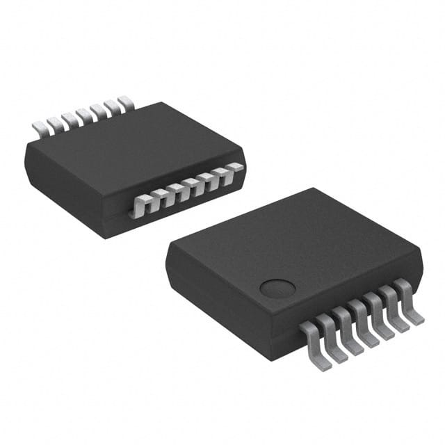
The 74HC125DB,112 is available in a small outline package (SO) with 14 pins. It is typically sold in reels or tubes containing multiple units.
Specifications
- Supply voltage: 2 V to 6 V
- Input voltage: 0 V to VCC
- Output voltage: 0 V to VCC
- Operating temperature range: -40°C to +125°C
- Maximum propagation delay: 15 ns
- Maximum quiescent current: 4 μA
Pin Configuration
┌───┐
   Y1 ─│1  14│─ VCC
   Y2 ─│2  13│─ A1
   GND ─│3  12│─ A2
   Y3 ─│4  11│─ A3
   Y4 ─│5  10│─ OE
   A4 ─│6   9│─ GND
   NC ──│7   8│─ NC
       └───┘
Functional Features
- The 74HC125DB,112 provides four independent buffer/line driver channels.
- Each channel has a 3-state output, allowing it to be connected to a bus or shared line.
- The Schmitt-trigger action on all inputs ensures improved noise immunity and hysteresis.
Advantages and Disadvantages
Advantages
- High-speed operation enables efficient data transfer.
- Wide operating voltage range allows compatibility with various systems.
- Low power consumption reduces energy requirements.
- Schmitt-trigger action enhances noise immunity.
Disadvantages
- Limited number of channels (four in total).
- Not suitable for applications requiring a large number of buffer/line driver channels.
Working Principles
The 74HC125DB,112 operates as a buffer/line driver by amplifying and buffering input signals. It provides a high impedance output when the output enable (OE) pin is set to a high logic level. When the OE pin is low, the buffered input signal is driven onto the corresponding output pin.
Application Field Plans
The 74HC125DB,112 finds applications in various fields, including: 1. Data communication systems 2. Industrial automation 3. Automotive electronics 4. Consumer electronics 5. Medical equipment
Alternative Models
Other alternative models that can be used as substitutes for the 74HC125DB,112 include: - SN74HC125N - MC74HC125AN - CD74HC125E - 74HCT125N
These alternative models offer similar functionality and characteristics, providing flexibility in design choices.
In conclusion, the 74HC125DB,112 is a quad buffer/line driver IC with 3-state outputs. Its high-speed operation, wide voltage range, and low power consumption make it suitable for various applications. However, its limited number of channels may restrict its use in certain scenarios. Designers can consider alternative models for similar functionality and characteristics.
技術ソリューションにおける 74HC125DB,112 の適用に関連する 10 件の一般的な質問と回答をリストします。
Sure! Here are 10 common questions and answers related to the application of 74HC125DB,112 in technical solutions:
Q: What is the 74HC125DB,112? A: The 74HC125DB,112 is a quad buffer gate IC (integrated circuit) that provides four independent buffer gates with tri-state outputs.
Q: What is the purpose of using the 74HC125DB,112 in technical solutions? A: The 74HC125DB,112 is commonly used for level shifting, signal buffering, and driving high-current loads in digital circuits.
Q: What is the voltage supply range for the 74HC125DB,112? A: The 74HC125DB,112 operates within a voltage supply range of 2V to 6V.
Q: How many input/output pins does the 74HC125DB,112 have? A: The 74HC125DB,112 has 14 pins, with each buffer gate having one input and one output pin.
Q: Can the 74HC125DB,112 handle both TTL and CMOS logic levels? A: Yes, the 74HC125DB,112 is compatible with both TTL (Transistor-Transistor Logic) and CMOS (Complementary Metal-Oxide-Semiconductor) logic levels.
Q: What is the maximum output current that the 74HC125DB,112 can provide? A: The 74HC125DB,112 can provide a maximum output current of 8mA per channel.
Q: Can the 74HC125DB,112 be used for bidirectional communication? A: No, the 74HC125DB,112 is unidirectional and can only be used for one-way signal buffering.
Q: What is the purpose of the tri-state outputs in the 74HC125DB,112? A: The tri-state outputs allow the buffer gates to be disabled, effectively disconnecting the output from the circuit, which can be useful for bus systems or multi-driver applications.
Q: Can the 74HC125DB,112 tolerate overvoltage on its inputs? A: No, the 74HC125DB,112 is not designed to tolerate overvoltage on its inputs and may get damaged if subjected to excessive voltage levels.
Q: Are there any specific precautions to consider when using the 74HC125DB,112? A: It is important to ensure proper decoupling capacitors are used near the power supply pins, avoid exceeding the maximum ratings, and follow the recommended operating conditions mentioned in the datasheet to ensure reliable operation.
Please note that these answers are general and may vary depending on the specific application and requirements. Always refer to the datasheet and consult with an expert for accurate information.