

PIC16C711-04/SO
Product Overview
Category
The PIC16C711-04/SO belongs to the category of microcontrollers.
Use
This microcontroller is commonly used in various electronic applications that require embedded control and processing capabilities.
Characteristics
- Low power consumption
- High performance
- Compact size
- Versatile functionality
Package
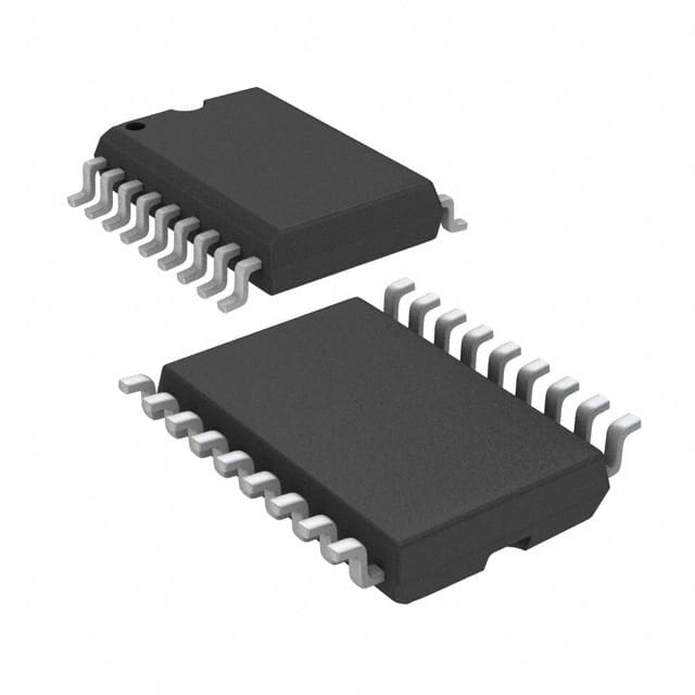
The PIC16C711-04/SO is available in a small outline (SO) package, which allows for easy integration into electronic circuits.
Essence
The essence of the PIC16C711-04/SO lies in its ability to provide efficient control and processing capabilities in a compact form factor.
Packaging/Quantity
The microcontroller is typically packaged in reels or tubes, with each containing a specific quantity of units. The exact packaging and quantity may vary depending on the supplier.
Specifications
- Architecture: 8-bit
- CPU Speed: 4 MHz
- Program Memory Size: 1.75 KB
- RAM Size: 64 bytes
- Number of I/O Pins: 13
- Operating Voltage Range: 2.5V - 5.5V
- Data Bus Width: 8 bits
- Timers: 1 x 8-bit, 1 x 16-bit
- Analog-to-Digital Converter (ADC): 4 channels, 10-bit resolution
Detailed Pin Configuration
The PIC16C711-04/SO features a total of 18 pins, each serving a specific purpose. The pin configuration is as follows:
- VDD - Power supply voltage
- RA0/AN0 - Analog input / Digital I/O
- RA1/AN1 - Analog input / Digital I/O
- RA2/AN2 - Analog input / Digital I/O
- RA3/AN3/VREF - Analog input / Digital I/O / Voltage reference
- RA4/T0CKI/C1OUT - Timer0 clock input / Digital I/O / Comparator output
- MCLR/VPP - Master Clear input / Programming voltage
- VSS - Ground
- RB0/INT - External interrupt input / Digital I/O
- RB1/SDI/SDA - SPI data input / I2C data input / Digital I/O
- RB2/SDO/SCL - SPI data output / I2C data output / Digital I/O
- RB3/PGM - Programming mode input / Digital I/O
- RB4/PGC - Programming clock input / Digital I/O
- RB5/PGD - Programming data input/output / Digital I/O
- RB6/OSC1/CLKIN - Oscillator input / Clock input
- RB7/OSC2/CLKOUT - Oscillator output / Clock output
- VDD - Power supply voltage
- VSS - Ground
Functional Features
The PIC16C711-04/SO offers a range of functional features, including:
- Central Processing Unit (CPU) with 8-bit architecture
- Flash program memory for storing instructions
- Random Access Memory (RAM) for temporary data storage
- Timers for precise timing control
- Analog-to-Digital Converter (ADC) for analog signal processing
- General-purpose input/output (GPIO) pins for interfacing with external devices
- Interrupt capability for handling time-sensitive events
- Low power consumption for energy-efficient operation
Advantages and Disadvantages
Advantages
- Compact size allows for easy integration into space-constrained designs
- Low power consumption extends battery life in portable applications
- Versatile functionality enables a wide range of applications
- Cost-effective solution for embedded control and processing needs
Disadvantages
- Limited program memory size may restrict the complexity of applications
- Limited RAM size may impose constraints on data storage and manipulation
- Lack of built-in communication interfaces may require additional components for certain applications
Working Principles
The PIC16C711-04/SO operates based on the principles of digital logic and microcontroller architecture. It executes instructions stored in its program memory, processes data using its CPU, and interacts with external devices through its I/O pins. The microcontroller can be programmed to perform specific tasks by writing appropriate instructions into its program memory.
Detailed Application Field Plans
The PIC16C711-04/SO finds applications in various fields, including but not limited to:
- Home automation systems
- Industrial control systems
- Automotive electronics
- Medical devices
- Consumer electronics
- Internet of Things (IoT) devices
- Robotics
- Security systems
Detailed and Complete Alternative Models
There are several alternative models available that offer similar functionality to the PIC16C711-04/SO. Some notable alternatives include:
- PIC
技術ソリューションにおける PIC16C711-04/SO の適用に関連する 10 件の一般的な質問と回答をリストします。
What is the operating voltage range of PIC16C711-04/SO?
- The operating voltage range of PIC16C711-04/SO is 2.0V to 5.5V.What is the maximum frequency at which PIC16C711-04/SO can operate?
- PIC16C711-04/SO can operate at a maximum frequency of 20 MHz.Can PIC16C711-04/SO be used in battery-powered applications?
- Yes, PIC16C711-04/SO's low operating voltage range makes it suitable for battery-powered applications.What are the key features of PIC16C711-04/SO?
- Some key features of PIC16C711-04/SO include 1.75K words of program memory, 64 bytes of data memory, and 35 I/O pins.Is PIC16C711-04/SO suitable for temperature-sensitive environments?
- Yes, PIC16C711-04/SO has a wide operating temperature range of -40°C to 125°C, making it suitable for temperature-sensitive environments.Can PIC16C711-04/SO be programmed using standard programming tools?
- Yes, PIC16C711-04/SO can be programmed using standard programming tools such as MPLAB® ICD 4 or PICkit™ 4.What communication interfaces does PIC16C711-04/SO support?
- PIC16C711-04/SO supports communication interfaces such as SPI, I2C, and USART.Is PIC16C711-04/SO suitable for motor control applications?
- Yes, PIC16C711-04/SO's high-speed PWM module and capture/compare capabilities make it suitable for motor control applications.Can PIC16C711-04/SO be used in automotive electronics?
- Yes, PIC16C711-04/SO is AEC-Q100 Grade 1 qualified, making it suitable for automotive electronics applications.Are there any development boards available for PIC16C711-04/SO?
- Yes, there are development boards available for PIC16C711-04/SO, such as the Curiosity Development Board.