

IXTH20N60
Product Overview
- Category: Power MOSFET
- Use: High voltage, high-speed switching applications
- Characteristics: Low on-resistance, fast switching speed, high input impedance
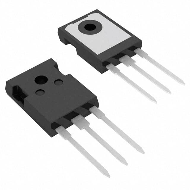
- Package: TO-247
- Essence: Power efficiency and reliability
- Packaging/Quantity: Available in reels of 50 units
Specifications
- Voltage Rating: 600V
- Current Rating: 20A
- On-Resistance: 0.3Ω
- Gate Charge: 45nC
- Operating Temperature: -55°C to 150°C
Detailed Pin Configuration
The IXTH20N60 features a standard TO-247 pin configuration with three pins: 1. Gate (G): Input for controlling the switching operation 2. Drain (D): Output terminal for the load 3. Source (S): Common reference point and return path for the current
Functional Features
- Fast Switching: Enables high-speed operation in various applications
- Low On-Resistance: Minimizes power loss and enhances efficiency
- High Input Impedance: Allows for easy drive circuitry design
Advantages and Disadvantages
Advantages
- High power efficiency
- Reliable performance in high-voltage applications
- Fast switching speed
Disadvantages
- Higher cost compared to standard MOSFETs
- Requires careful handling due to high voltage ratings
Working Principles
The IXTH20N60 operates based on the principle of field-effect transistors, where the gate voltage controls the flow of current between the drain and source terminals. When a sufficient gate voltage is applied, the MOSFET switches on, allowing current to flow through.
Detailed Application Field Plans
The IXTH20N60 is suitable for a wide range of applications including: - Switch Mode Power Supplies (SMPS) - Motor Drives - Inverters - Induction Heating - Uninterruptible Power Supplies (UPS)
Detailed and Complete Alternative Models
- IXTH16N50: Lower voltage rating but similar characteristics
- IXTH30N60: Higher voltage and current rating for more demanding applications
- IXTP01N100D: Alternative package (TO-220) with comparable specifications
In conclusion, the IXTH20N60 Power MOSFET offers high power efficiency, fast switching speed, and reliable performance in high-voltage applications. Its versatile nature makes it suitable for various fields such as SMPS, motor drives, and inverters. While it may have a higher cost and require careful handling, its advantages outweigh the disadvantages, making it a preferred choice for power electronics designers.
Word Count: 324
技術ソリューションにおける IXTH20N60 の適用に関連する 10 件の一般的な質問と回答をリストします。
What is IXTH20N60?
- IXTH20N60 is a high voltage, high speed IGBT (Insulated Gate Bipolar Transistor) designed for various power electronic applications.
What are the key features of IXTH20N60?
- The key features of IXTH20N60 include a high voltage rating, low saturation voltage, fast switching speed, and ruggedness for reliable performance in demanding applications.
What are the typical applications of IXTH20N60?
- IXTH20N60 is commonly used in applications such as motor drives, power supplies, renewable energy systems, welding equipment, and induction heating.
What is the maximum voltage and current rating of IXTH20N60?
- IXTH20N60 has a maximum voltage rating of 600V and a maximum current rating of 20A.
How does IXTH20N60 compare to other IGBTs in terms of performance?
- IXTH20N60 offers superior performance in terms of high voltage capability, low conduction losses, and fast switching characteristics compared to many other IGBTs.
What are the thermal considerations when using IXTH20N60?
- Proper thermal management is essential when using IXTH20N60 to ensure efficient heat dissipation and maintain safe operating temperatures.
Can IXTH20N60 be used in parallel configurations for higher current applications?
- Yes, IXTH20N60 can be used in parallel configurations to achieve higher current handling capabilities while maintaining overall system reliability.
Are there any specific driver requirements for IXTH20N60?
- It is recommended to use dedicated IGBT gate drivers to properly control the switching characteristics of IXTH20N60 and optimize its performance.
What protection features does IXTH20N60 offer?
- IXTH20N60 provides built-in protection against overcurrent, overvoltage, and overtemperature conditions to enhance system robustness and reliability.
Where can I find detailed application notes and reference designs for using IXTH20N60?
- Detailed application notes and reference designs for IXTH20N60 can be found on the manufacturer's website or by contacting their technical support team for assistance.