Encyclopedia Entry: 74AHC595S16-13
Product Overview
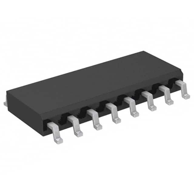
The 74AHC595S16-13 is an integrated circuit (IC) belonging to the category of shift registers. It is widely used in various electronic devices and systems for its ability to efficiently control multiple outputs using a minimal number of pins. This IC exhibits several characteristics that make it highly versatile and suitable for a range of applications. The 74AHC595S16-13 is typically packaged in a small outline integrated circuit (SOIC) package, which ensures ease of handling and compatibility with standard manufacturing processes.
Specifications
- Category: Shift Register
- Use: Control multiple outputs
- Characteristics: Versatile, compact design
- Package: Small Outline Integrated Circuit (SOIC)
- Essence: Efficient output control with minimal pin usage
- Packaging/Quantity: Typically sold in reels or tubes containing multiple units
Pin Configuration
The 74AHC595S16-13 features a total of 16 pins, each serving a specific function. The detailed pin configuration is as follows:
- Serial Data Input (DS)
- Serial Data Output (QH')
- Serial Clock Input (SHCP)
- Storage Register Clock Input (STCP)
- Master Reset Input (MR)
- Output Enable Input (OE')
- Q0 Output
- Q1 Output
- Q2 Output
- Q3 Output
- Q4 Output
- Q5 Output
- Q6 Output
- Q7 Output
- Ground (GND)
- Supply Voltage (VCC)
Functional Features
The 74AHC595S16-13 offers several functional features that enhance its usability and performance. These include: - Serial-to-parallel data conversion - Cascading capability for controlling multiple ICs in series - Output enable/disable functionality for power management - Master reset option for clearing the shift register - High-speed operation with minimal propagation delay
Advantages and Disadvantages
Advantages: - Efficient utilization of pins for controlling multiple outputs - Compact design suitable for space-constrained applications - Easy integration into existing electronic systems - High-speed operation for time-critical applications
Disadvantages: - Limited number of output pins (8 in total) - Requires additional components for voltage regulation and protection
Working Principles
The 74AHC595S16-13 operates based on the principle of serial data shifting and parallel data storage. It receives serial data input, which is then shifted through the internal registers using clock signals. The shifted data is stored in the output latch, allowing simultaneous control of multiple outputs. The IC can be cascaded to control an extended number of outputs by connecting the serial output of one IC to the serial input of another.
Application Field Plans
The 74AHC595S16-13 finds extensive application in various fields, including: 1. LED matrix displays 2. Seven-segment displays 3. Digital clocks 4. Data multiplexing 5. Industrial automation systems 6. Robotics 7. Automotive electronics
Alternative Models
For users seeking alternative options, several models similar to the 74AHC595S16-13 are available in the market. These include: - 74HC595 - SN74HC595 - CD74HC595 - M74HC595
These alternatives offer comparable functionalities and pin configurations, providing flexibility in choosing the most suitable option for specific applications.
In conclusion, the 74AHC595S16-13 is a versatile shift register IC that enables efficient control of multiple outputs. Its compact design, high-speed operation, and cascading capability make it an ideal choice for various electronic applications.
技術ソリューションにおける 74AHC595S16-13 の適用に関連する 10 件の一般的な質問と回答をリストします。
Sure! Here are 10 common questions and answers related to the application of 74AHC595S16-13 in technical solutions:
Q: What is the 74AHC595S16-13? A: The 74AHC595S16-13 is a shift register IC (integrated circuit) that can be used to expand the number of digital outputs in a microcontroller or other digital system.
Q: How does the 74AHC595S16-13 work? A: The 74AHC595S16-13 uses serial input and parallel output to shift data through its internal registers. It has a clock input, a data input, and a latch enable input to control the shifting and storage of data.
Q: What is the maximum clock frequency supported by the 74AHC595S16-13? A: The 74AHC595S16-13 can support clock frequencies up to 100 MHz.
Q: How many digital outputs can be controlled using a single 74AHC595S16-13? A: The 74AHC595S16-13 can control up to 8 digital outputs.
Q: Can multiple 74AHC595S16-13 chips be cascaded together to control more than 8 outputs? A: Yes, multiple 74AHC595S16-13 chips can be cascaded together to control a larger number of outputs. This is commonly referred to as "daisy-chaining" the chips.
Q: What is the power supply voltage range for the 74AHC595S16-13? A: The 74AHC595S16-13 operates with a power supply voltage range of 2 V to 6 V.
Q: Can the 74AHC595S16-13 be used with both CMOS and TTL logic levels? A: Yes, the 74AHC595S16-13 is compatible with both CMOS and TTL logic levels.
Q: What is the maximum output current that can be sourced or sunk by each output pin of the 74AHC595S16-13? A: The 74AHC595S16-13 can source or sink up to 35 mA of current per output pin.
Q: Does the 74AHC595S16-13 have any built-in protection features? A: Yes, the 74AHC595S16-13 has built-in ESD (electrostatic discharge) protection on all inputs and outputs.
Q: Are there any specific application notes or reference designs available for using the 74AHC595S16-13 in technical solutions? A: Yes, the manufacturer of the 74AHC595S16-13 typically provides application notes and reference designs that can help guide the implementation of the IC in various technical solutions. These resources can be found on their website or in the datasheet provided with the IC.
Please note that the answers provided here are general and may vary depending on the specific requirements and datasheet of the 74AHC595S16-13.


