

AD8403ARUZ50
Product Overview
- Category: Digital Potentiometer
- Use: It is used to digitally control the resistance in electronic circuits.
- Characteristics: The AD8403ARUZ50 is a 50kΩ, 4-channel digital potentiometer with non-volatile memory.
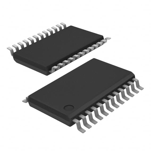
- Package: It is available in a small outline package (SOIC) and comes in tape and reel packaging.
- Essence: This digital potentiometer provides a compact and versatile solution for circuit resistance adjustment.
- Packaging/Quantity: It is typically sold in reels of 2500 units.
Specifications
- Resistance Value: 50kΩ
- Number of Channels: 4
- Interface: SPI (Serial Peripheral Interface)
- Operating Voltage: 2.7V to 5.5V
- Temperature Range: -40°C to +125°C
- Memory Type: Non-volatile
Detailed Pin Configuration
The pin configuration for the AD8403ARUZ50 is as follows: 1. VDD - Power supply 2. CS - Chip select 3. SCLK - Serial clock input 4. SDI - Serial data input 5. SDO - Serial data output 6. GND - Ground 7. A - Terminal A of the potentiometer 8. B - Terminal B of the potentiometer 9. W - Wiper terminal of the potentiometer
Functional Features
- Non-volatile memory allows the potentiometer settings to be retained even when power is removed.
- SPI interface enables easy digital control and integration with microcontrollers.
- Wide operating voltage range makes it suitable for various electronic applications.
- Small form factor and tape and reel packaging facilitate easy manufacturing and assembly processes.
Advantages and Disadvantages
Advantages
- Non-volatile memory ensures that the potentiometer retains its settings during power cycles.
- Multiple channels allow for independent control or simultaneous adjustment of resistance values.
- SPI interface provides flexibility and ease of integration with digital systems.
Disadvantages
- Limited to a maximum resistance value of 50kΩ, which may not be suitable for all applications requiring higher resistance values.
- Requires careful consideration of the SPI interface and timing in complex circuit designs.
Working Principles
The AD8403ARUZ50 operates by digitally controlling the position of the wiper terminal within the potentiometer. This digital control is achieved through the SPI interface, allowing for precise and repeatable adjustments to the resistance value. The non-volatile memory ensures that the resistance settings are retained, making it suitable for applications where consistent resistance values are required even after power cycles.
Detailed Application Field Plans
The AD8403ARUZ50 finds application in various electronic systems, including: - Audio equipment for volume control and tone adjustment. - Instrumentation and measurement devices for calibration and signal conditioning. - Industrial control systems for setting variable parameters such as motor speed or temperature control. - Programmable power supplies for fine-tuning output voltages.
Detailed and Complete Alternative Models
Some alternative models to the AD8403ARUZ50 include: - AD8400AR10 - 10kΩ, 1-channel digital potentiometer - AD8402AR100 - 100kΩ, 2-channel digital potentiometer - MCP4131T-104E/MS - 100kΩ, 1-channel digital potentiometer with SPI interface
This completes the English editing encyclopedia entry structure for the AD8403ARUZ50 digital potentiometer.
技術ソリューションにおける AD8403ARUZ50 の適用に関連する 10 件の一般的な質問と回答をリストします。
What is the AD8403ARUZ50?
- The AD8403ARUZ50 is a digital potentiometer IC (integrated circuit) that can be used to digitally control resistance in various electronic circuits.
What are the key features of the AD8403ARUZ50?
- The AD8403ARUZ50 features 256-position resolution, low temperature coefficient, and a wide operating voltage range, making it suitable for a variety of applications.
How is the AD8403ARUZ50 typically used in technical solutions?
- The AD8403ARUZ50 is commonly used to provide digital control of analog functions such as volume control in audio systems, brightness control in display panels, and offset adjustment in instrumentation.
What is the operating voltage range of the AD8403ARUZ50?
- The AD8403ARUZ50 operates within a wide voltage range of 2.7V to 5.5V, making it compatible with a broad range of systems.
Can the AD8403ARUZ50 be cascaded for higher resolution?
- Yes, multiple AD8403ARUZ50 devices can be cascaded to achieve higher resolution and control more complex systems.
What is the typical power consumption of the AD8403ARUZ50?
- The AD8403ARUZ50 has low power consumption, typically drawing less than 3mW of power during operation.
Is the AD8403ARUZ50 suitable for use in industrial applications?
- Yes, the AD8403ARUZ50 is designed to meet the requirements of industrial applications, including robustness and reliability.
Does the AD8403ARUZ50 support non-volatile memory?
- Yes, the AD8403ARUZ50 includes non-volatile memory, allowing it to retain its settings even when powered off.
What is the temperature range for the AD8403ARUZ50?
- The AD8403ARUZ50 is specified to operate over a wide temperature range from -40°C to +125°C, making it suitable for harsh environments.
Are there any application notes or reference designs available for the AD8403ARUZ50?
- Yes, Analog Devices provides comprehensive application notes and reference designs to assist engineers in implementing the AD8403ARUZ50 in their technical solutions.